|

|
This Band Pass Filter (BPF) kit is for receiver input filtering. It uses the popular double-tuned-circuit which is reliable and easy to build, without needing access to any special equipment. Kits are available for 10 HF bands 160, 80, 60, 40, 30, 20, 17, 15, 12, and 10m. The kit uses a high-quality double-sided PCB with silk-screen, solder-mask and through-hole plating. The capacitors supplied with the kit are high-quality RF ceramics of the C0G type (a.k.a. NP0 - near-zero temperature coefficient). Designed for the relay-switched LPF kit, or your own projects! |

The Band Pass Filter kit is the same size as our LPF kit, 1.5 x 0.5 inches (38.1 x 12.7mm). The kit can therefore be used with our relay-switched filter kit. It has a 50-ohm input and output impedance. Please read the kit-building instructions (see below) for more details on the circuit, design trade-offs, construction, and adjustment procedures.
Assembly instructions
Printed instructions are NOT supplied with the kit. You can download the kit-building instructions for your PCB from the links below.
CLICK HERE to download the kit-building instructions for the BPF kit.
FRENCH TRANSLATION Click Here, assembly guide in French, by Michel ON4LAU
Kit photographs


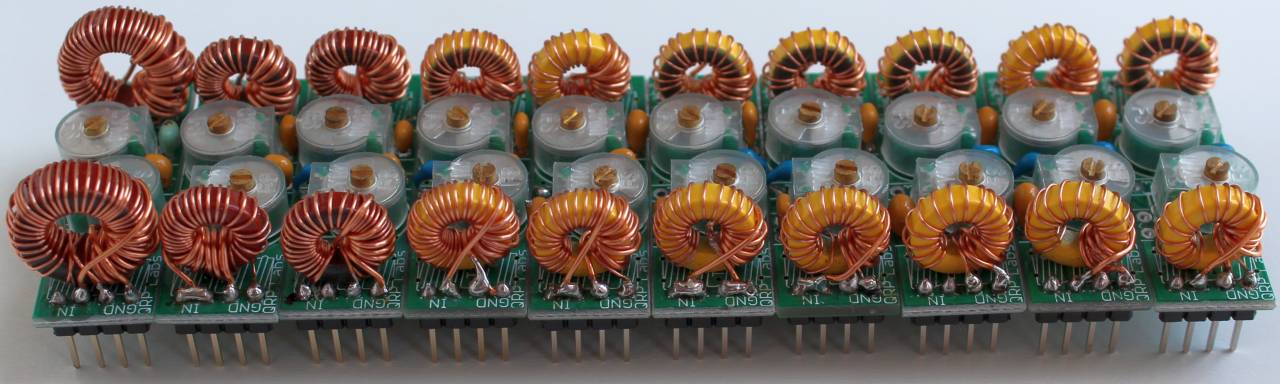
10-band set!
Here's the full array of 10 BPF kits, one for each HF band from 160m to 10m. Spoil yourself! EASY ORDER, one-click set, here!


Measured performance characteristics
The components and suggested toroid turns etc have been designed for a -3dB bandwidth of approximately one tenth of the centre frequency, and an insertion loss of better than 2dB. This means that the filters are suitable for each whole amateur band, including CW, QRP and SSB segments. In the spectrum analyser photographs below the "height" of the screen is 80dB. So you can see, away from the passband the attenuation reaches 60-80dB in most cases.
Note also that the filters have 50 ohm input/output impedance and could be cascaded together if required.
Of course, you may vary the component values to change or experiment with the characteristics! The kits were constructed as shown in the above photographs and in accordance with the parts list provided in the assembly instructions. The following measurements indicate the behaviour that should be expected from this kit.
| Band | Centre frequency | Bandwidth | Insertion |
| 160m | 1.867 MHz | 0.226 MHz | -1.45 dB |
| 80m | 3.540 MHz | 0.465 MHz | -1.27 dB |
| 60m | 5.243 MHz | 0.486 MHz | -1.48 dB |
| 40m | 7.207 MHz | 0.793 MHz | -1.53 dB |
| 30m | 9.891 MHz | 1.15 MHz | -1.35 dB |
| 20m | 14.15 MHz | 1.44 MHz | -1.75 dB |
| 17m | 18.22 MHz | 1.63 MHz | -1.95 dB |
| 15m | 21.00 MHz | 1.54 MHz | -1.10 dB |
| 12m | 25.53 MHz | 2.87 MHz | -1.55 dB |
| 10m | 28.99 MHz | 3.01 MHz | -2.52 dB |


Don't use these Band Pass Filters as a transmitter output filter!
The filters are designed for receiver input band pass filtering. They have a quite narrow response. The double-tuned circuit with transformer match results in an impedance step-up from the 50-ohms input/output. As a result the voltage in the centre section will be higher. In a receiver this is Ok but if you are using it in a transmitter, the higher voltage will exceed the rating of the capacitors and could lead to failure.
Furthermore, the filters have around 2dB of insertion loss. You will not want to be losing that much power from a transmitter output. And the lost power will be dissipated in the BPF as heat and also likely lead to failure.
It may be Ok to use the band pass filter in an early stage of a transmitter output signal chain where power levels are very low. For example you may wish to use a Band Pass Filter after a mixer to eliminate unwanted mixing products above and below the wanted output.
At a transmitter output always use a Low Pass Filter, whose purpose is to attenuate harmonics of the output frequency. The QRP Labs Low Pass Filters are designed to handle at least 10W power and the attenuation at the operating frequency should be very low.
Toroid-winding tutorial video
Thanks to Chris WX5CW for sending a link to this useful video showing one way to wind toroids!
6m Band Pass Filter test, by Euan M0GBZ
Euan writes:
Started with the 12m BPF kit and removed transformer primary turns until there was a well defined peak near the centre with both trimmers. T1 and T2: 3:12t, and no C2, C5 or C4.
Plotted filter response for two values of the coupling capacitor C3 (3pF and 1.2pF) - see attached files. The double peak vanishes with the reduced value.
Test setup: an Elecraft XG3 signal generator into the BPF into a 50 ohm dummy load, with scope measuring the output pp and converting to dB. I've no way of checking the input and output impedance.


