Summary
- Scope: Older QLG2 and QLG3 modules (QLG3 shipped before 20-Aug-2025 - but see below, QLG2 Rev 1 PCB with the larger E108-GN01 module), QLG2-SE module.
- Problem root: Bug in the GK9501 GNSS chip used in the EByte E108 module due to incorrect handling of week code rollover.
- Symtom: Incorrect dates 19.6 years ago are intermittently displayed and the 1pps output is not stable.
- Resolution: This page documents how to install a firmware update into the E108 module, provided by EBtyte, which completely fixes the problem (Flash Tool software is a Windows executable, but runs under WINE on Linux).
All QLG2 with the smaller module, and all QLG3 shipped after 20-Aug-2025, do NOT have this issue, and this article does not apply! The earlier QLG1 which uses a different GPS module, also does NOT have this issue!
Contents
Affected units
Issue background
Investigation
QLG3: Installing the new GNSS firmware on the E108 using QMX+ and Windows software (also works on Linux)
QLG2: Installing the new GNSS firmware on the E108 using QLG2 and Windows software (also works on Linux)
QLG2-SE firmware update
Affected units
Any QLG3 shipped before 20-Aug-2025 could have an E108 module with the firmware bug. Modules shipped after 20-Aug-2025 definitely have the latest firmware and do NOT have this issue.
QLG3 modules shipped before 20-Aug-2025 may or may not have this bug in the E108 module; it appears that the previous batch had the latest E108 firmware in the module and doesn't have the bug. It's best to make observations to determine whether or not you are affected. If the date shows intermittently as a date in 2006, or if the 1pps comes and goes, and number of satellites fluctuates wildly, then that means your E108 GNSS module has the firmware bug described below.
Any QLG2-SE (without the microcontroller) probably has the older E108 module and does have the firmware problem described below.
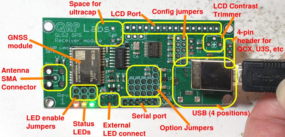
Any QLG2 with the older E108 module, which is called E108-GN01, and is a Rev 1 QLG2 PCB. These QLG2 GPS modules look like this:
PROBLEM QLG2:
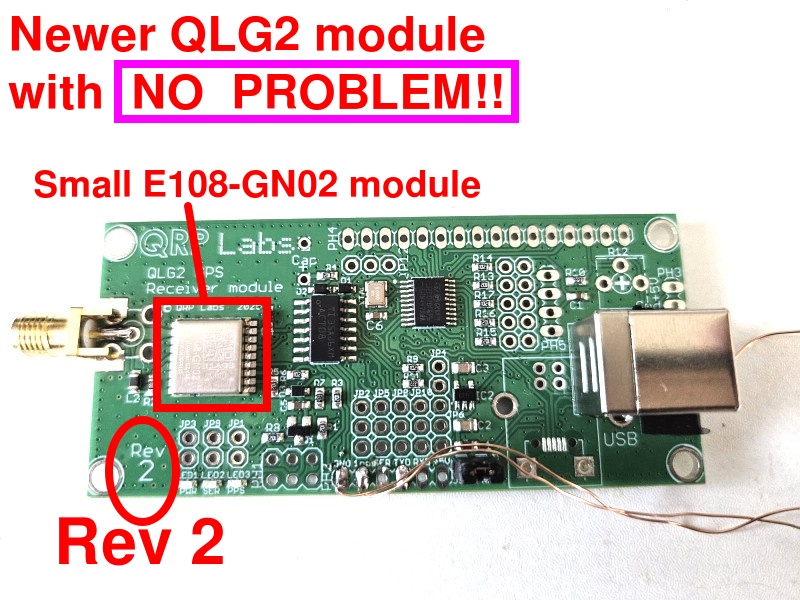
The more recent QLG2 modules are Rev 2, these use the smaller 10 x 10mm E108-GN02 module, as pictured below. These modules DO NOT have any firmware problem! This article does NOT apply to these recent QLG2 modules!
Issue background
On 17-Aug-2025, QLG2 and QLG3 GNSS receiver modules show an intermittent incorrect date from January 2006.
Apparently the way GPS satellites keep time, is the number of seconds in a week, and the number of weeks since a particular epoch. The week counter is a 10-bit variable, which means it rolls over to zero every 1024 weeks, being 19.6 years. Apparently, newer systems have 13-bit week codes which means they roll over far less often. See: https://en.m.wikipedia.org/
See also: https://uniguardgps.com/mt2503/
and https://github.com/traccar/traccar/issues/5634
Both the QRP Labs QLG2 and QLG3 use the eByte E108 module which itself contains the GK9501 GNSS chip. The older QRP Labs QLG1 uses a YIC GPS chip and doesn't have any problems. The E108 module can track two satellite constellations, by default GPS (US) and Beidou (China).
I believe what happened is that the older GPS system or some satellites in it, are using a 10-bit week code which recently rolled over to zero. The module firmware notices this and corrects for it. However it appears the newer Chinese Beidou satellites use a 13-bit week code. My feeling based on my observations is that as soon as a Chinese satellite joins the position fix calculation, the whole thing goes wrong because the module firmware is applying the same rollover compensation offset to dates from both systems (US and Chinese). Within a few seconds the firmware experiences some kind of internal error and resets itself, restarting the whole satellite acquisition process. Unfortunately the 1pps signal is present only for a few seconds, after the 3D fix and before the recurring self-respect that repeats the whole cycle. So this issue affects not only the date, but also the 1pps signal.
It can easily be observed that there is no fault in any of the QRP Labs firmwares, by observation of the raw serial data. It has also been demonstrated that issuing the command to the E108 module to switch off the Beidou (or GPS) constellation resolves the problem: there is only the incorrect date and recurring reset when both satellite constellations are used (which is the default).
Investigation
The problem was easy to see on a QMX+ with installed QLG3, running the GPS Viewer screen in the terminal. We tried to replicate it also with a QLG2 but the QLG2 behaved correctly! This is good news and showed that the current batch of QLG2s being shipped has no issue, which are the Rev 2 PCB with the smaller E108-GN02 module (10 x 10 mm module).
Ebyte technical support were very helpful and provided a Flash Tool executable and a new firmware binary, to flash into the misbehaving E108 chips. Our QRP Labs intern Cem did a lot of work on this too.
 I devised a way to make the QMX+ be the hardware interface between a PC running the Flash Tool, and the QMX+ installed in it. The normal connection of a QLG3 in QMX+ has only two signals from the module: Serial data out, and 1pps out. There is no connection to send serial data IN to the E108 GNSS module on the QLG3 board. So this was the first problem to overcome. The solution to this is to connect a wire from the TX pin of the neighboring AUX connector at the rear of the QMX+, to pin 3 (RX data). I wrote code in firmware 1_02_005 to be able to route incoming data from the USB Virtual COM port, to the AUX Serial port and from there to the E108 module. The data in the other direction travels the normal way via the regular GPS data streaming feature in QMX+. So this is a bit weird since one UART peripheral is doing the data transmit, and another is doing data receive; but from the top level perspective (the Flash Tool running on a PC host), it doesn't care.
A particularly difficult issue was that the Flash Tool specifies an initial baud rate of 9,600 baud (the E108 default at power-up) but then the firmware flash speed has a set of selectable speeds, the slowest of which is 115,200 baud. So at some point the communication has to change the UART baud rates. But WHAT point, was the question...
To get this working I had to develop tools to monitor serial port traffic in both directions. I used two channels on my oscilloscope to observe the serial traffic. I added a log of the serial traffic to another Virtual COM serial port so I could see where the problems occurred.
We had observed that command string $PGKC75*1D<CR><LF> was sent to the module by the Flash Tool. Unfortunately no EByte documentation on the GK9501 chip listed this command. But famous QRP Labs intern Cem did research and found this Quectel documentation on the firmware update procedure for their LC76F GNSS module: https://www.quectel.com/content/uploads/2024/02/Quectel_LC76F_Firmware_Upgrade_Guide_V1.0.pdf - this document was absolutely key to unlocking the mysteries of this firmware update procedure. The observed data traffic between the E108 and the FlashTool host did NOT exactly match the Quectel document but it was close enough that it eventually helped us solve all the issues.
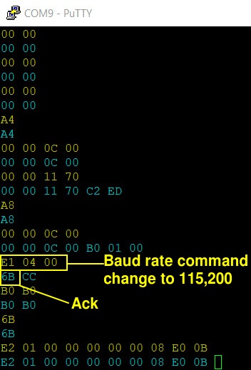
In the screenshot (right), the byte hex data written in Yellow is sent from the PC Host (Flash tool) to the E108; the replies from the E108 to the PC host are in blue. This was actually at the FINAL point of the investigation - at this point the Flash Tool had transferred to the module the "Burn Engine" code and the highlighted commands are what tells the module to change its baud rate to 115,200 baud. The 0x6B answer from the module is the acknowledgement. After this, both the QMX+ Send and Receive UART have to be re-configured from 9,600 baud to 115,200 baud because this is what the E108 module is subsequently using. In the remaining lines of that screenshot there is some confusion, the module apparently replies to host commands with echo of the sent command, which is NOT the expected response (and in fact I don't even understand how that response is possible), and finally the Flash Tool aborts the attempt. As soon as I watched for the sequence 0xE1 0x04 0x00 from the host, and the 0x6B response from the module, the Flash process completed successfully (new firmware installed!).
So bit by bit, with oscilloscope and USB serial log assistance, we were able to iron out the difficulties one by one, and make the QMX+ firmware now able to act as the interface between the E108 and the PC Host.
It should be noted that another way to do this would probably (not tested!) be with one of those FTDI or similar USB to Serial converters, which have proprietary drivers and are able to change the baud rate of their UART based on commands from the PC host. This doesn't apply to the Virtual USB COM serial port device in QMX+, which is why it has to monitor the serial traffic looking for that baud rate change command, then action it on the QMX+ peripherals. It was important to do it this way because now anyone with a QLG3 in a QMX+ can easily update the E108 module firmware.
Key summary:
- The QMX+ has an optional GNSS module, QLG3
- The QLG3 module has GNSS receiver module, E108-GN02, made by Ebyte
- The Ebyte E108 module contains a GK9501 GNSS engine chip
- The GK9501 GNSS engine chip had firmware problems that have a vulnerability to the date week code rollover that happened on 17-Aug-2025.
- QRP Labs Rev 2 QLG2 GPS and all QLG3 modules supplied since 20-Aug-2025, and even those in the batch preceding this, do NOT have this issue, because they already use a later version of the GK9501 firmware.
Special thanks to Helen at EByte and our QRP Labs intern Cem.
QLG3: Installing the new GNSS firmware on the E108 using QMX+ and Windows FlashTool software (also works on Linux)
Here I will document the steps to install the new firmware on the GK9501 chip in the E108 module which is in the QLG3 module which is in the QMX+. For fixing a QLG2 module, this is dealt with in a subsequent section of this page.
None of this is DIFFICULT, anyone can easily do it, but it does require that the following steps are followed precisely and carefully. Any incorrect configuration, will probably result in failure. If you follow these steps precisely, you should be able to update the firmware in your QLG3 module.
READ CAREFULLY!!!
1. Install QMX+ firmware 1_02_005 or above
You at least version 1_02_005 (released on 23-Aug-2025). You can download this here. Follow the instructions in the QMX operating manual to update the firmware.
2. Download the EByte Flash tool and firmware update
The Flash Tool and firmware update are a .zip file, if you click this link below, you should be able to download the file:
https://e.pcloud.link/publink/show?code=XZDK0OZb7ujj920vYQWGNIGbRB7RF5bUBzX
On clicking this link you should come to a web page looking something like the screenshot below. Click the download icon circled in the picture, to download the zip file.
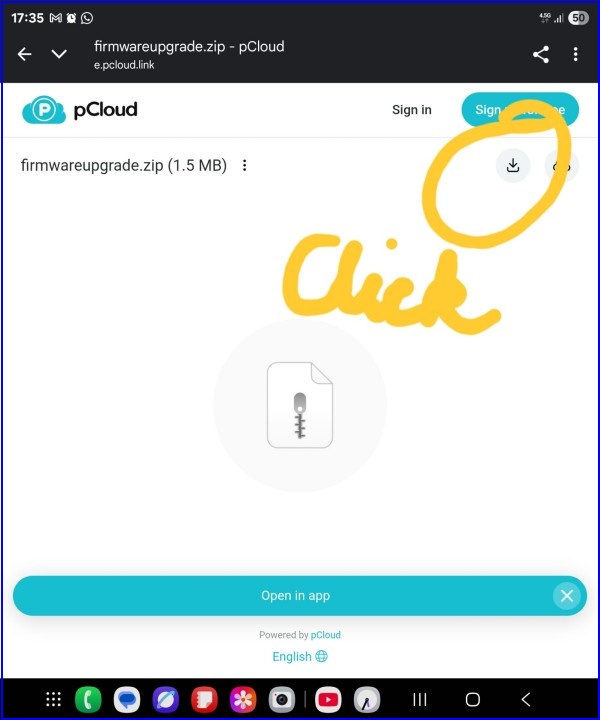
Note that this Flash Tool is a Windows Executable, however It does work correctly on Linux using WINE. More on this below. Note that this Flash Tool and the firmware update binary file are hosted at this shared location with permission from Helen at EByte.
Anyway, download the .zip file and unzip it to some convenient location on your computer.
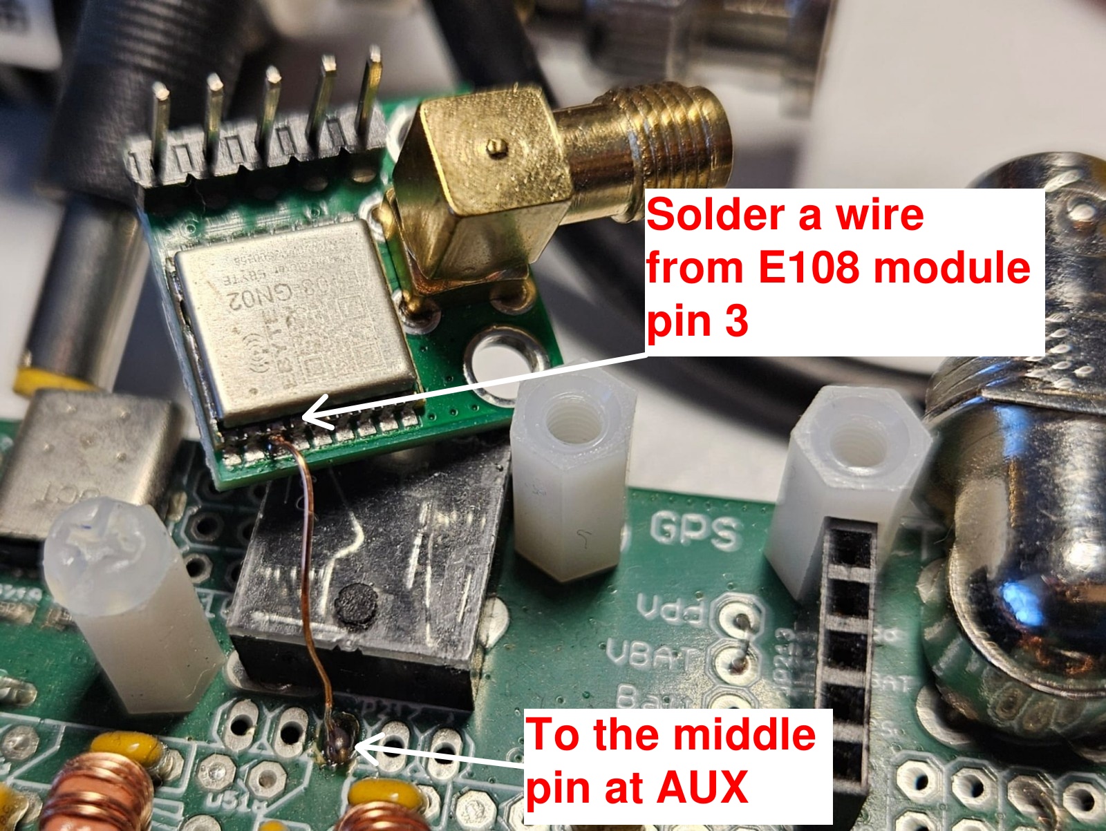
3. Connect a wire from the AUX TX pin to the QLG3 E108
You need to connect a piece of wire (I used the usual QRP Labs 0.33mm enameled copper wire) from pin 3 of the E108 module, to the middle pin of the adjacent AUX jack pin header connector, as shown in the photograph below. Then re-assemble the QLG3 and QMX+.
4. Configure QMX+
Remember that you MUST have firmware 1_02_005 or greater. You also need to connect the USB cable to your PC before switching on the QMX+. So do all that, power up your QMX+; and connect a terminal emulator to your QMX+ (such as PuTTY); if you have not done this before please refer to the operating manual.
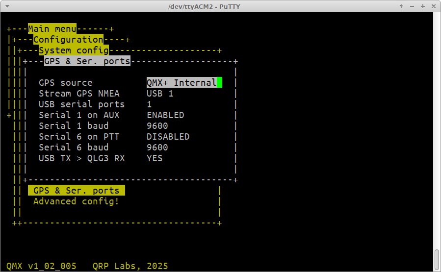
Navigate to the Configuration / System config / GPS & Ser. ports screen:
You need to configure several settings in this screen correctly, to make this work.
Note that this can be done with ONE USB serial port, you do not need to enable 2 or 3. But since it does involve switching on streaming of GPS NMEA data to the USB Serial port *USB 1", you will not then be able to connect with a terminal and edit the configuration back to disable this subsequently. You can still do it on the QMX+ LCD. But if you want to be able to do it on the QMX+ via a terminal connection then it would be best to enable multiple serial ports (2, or 3).
It's a good idea to take a screenshot of this screen before you edit it - so that later on you can put things back to how they were.
The critical settings are:
- "GPS source" must be set to "QMX+ Internal". This is so that the internal QLG3 GPS is being used, not an external GPS plugged into the paddle port.
- "Stream GPS NMEA" must be set to "USB 1".
- "Serial 1 on AUX" must be set to "ENABLED".
- "Serial 1 baud" must be set to "9600".
- "USB TX > QLG3 RX" must be set to "YES".
Other settings in this menu are not relevant to this procedure, and can be left alone. Only the five items listed above need to be set up exactly this way. Again: this has to all be set up EXACTLY like this, otherwise the process is not going to work! Furthermore, after making changes in this menu, always remember to switch QMX+ off and on again, because some of the settings in this menu only take effect on power-up.
5. Run the Flash Tool program sent by EByte
Double clicking the program in whatever folder you unzipped it to, should run the FlashTool.
On LINUX systems you may also use the FlashTool.exe although it is a Windows executable, by using WINE. On my system, I had downloaded the zip file, unzipped it, and renamed it to "FlashTool.exe", this file sat in the Downloads folder. At a terminal prompt I typed "cd Downloads" to set the directory to my Downloads folder, then simply "wine FlashTool.exe". A number of error complaints are then shown, involving missing DLL's and such, but the tool actually works anyway regardless of these error reports.
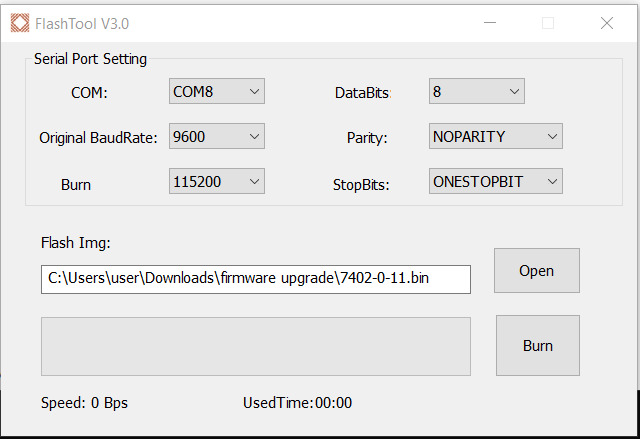
The configuration of this tool is critical to success!
You need to do the following configuration:
- "COM": Select the COM port to whatever serial port corresponds to "USB 1" on the QMX+. If you have enabled multiple USB ports on your QMX+ (the "USB serial ports" setting in the "GPS & Ser. ports" screen, you have to select the correct one. It's the first port, where the GPS NMEA serial data is streamed to. This whole process is set up to only work on that first USB serial port.
- "Original BaudRate" must be set to "9600".
- "Burn" must be set to "115200", this is the baud rate at which the firmware is Flashed. Only 115200 is supported by the QMX+, in this firmware flashing application.
- Click the "Open" button, and navigate to the folder where you unzipped the downloaded firmware, and select that firmware file 7402-0-11.bin.
The DataBits, Parity and StopBits settings are of no consequence and can be left at their defaults.
One very common cause of problems, is failure to select the correct COM port. This is the case on both Windows and Linux systems. The COM port must be the one where the GPS serial data is streamed to. You can check this by opening a Putty Terminal emulator session connected to the port. You should see the NMEA data scrolling up the screen. Then make sure you close the Putty Terminal emulator session to release the port.
On LINUX systems the way WINE maps the ports is not obvious. You can actually type the command "ls -l ~/.wine/dosdevices/" and this will display the whole list of devices on the system, and what they are mapped to in WINE. Assuming for example, that on Linux the QMX+ Serial port is at /dev/ttyACM0 then you can look at the list and find out what COM port number this is. In my system, /dev/ttyACM0 maps to COM33 so in the drop down in the FlashTool, I select COM33.
When all is done, your FlashTool program will look something like the below. Your COM port setting and your Flash Img. file location will be different to mine, depending on your system.
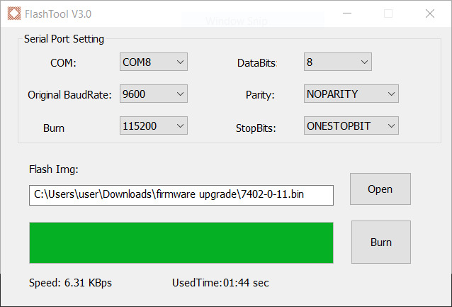
6. Run the Flash tool
When you are 100% sure that you have done all previous steps correctly, really, 100% sure (please re-check twice), take a deep breath, and hit the "Burn" button on the Flash Tool. Now don't breathe, don't blink, don't think of anything, just watch anxiously... and if all is well, you should see a green progress bar, ever expanding. In the end after a little less than 2 minutes, you should get a popup message that the Flashing has successfully completed.
7. Power down QMX+ and restart it
This is necessary because after the Flash process, the QLG3 module is still in 115,200 baud rate mode. Rebooting will set everything back to the usual 9600 baud. You can also now edit the "GPS & Ser. ports" menu items to put them back to how they were before you played with all this. Make sure that the "USB TX > QLG3 RX" must be set to "NO" now. You may also remove the wire from the AUX connector to the QLG3 E108 module pin 3. Finally, when making any changes in the serial config menu, switch QMX+ on and off again, since some changes only take effect at power-up.
Now you can go to the GPS Viewer screen and verify that the QLG3 is now functioning correctly, without any date error or reset cycle restarting the satellite acquisition.
QLG2: Installing the new GNSS firmware on the E108 using QLG2 and Windows software (also works on Linux)
Here I will document the steps to install the new firmware on the GK9501 chip in the E108 module which is in the QLG2 module. For fixing a QLG3 module, this is dealt with in a previous section of this page.
None of this is DIFFICULT, anyone can easily do it, but it does require that the following steps are followed precisely and carefully. Any incorrect configuration, will probably result in failure. If you follow these steps precisely, you should be able to update the firmware in your QLG2 module.
READ CAREFULLY!!!
1. Install QLG2 firmware 1_01 or above
You at least version 1_01 (released on 10-Sep-2025). You can download this here. Follow the instructions in the QLG2 operating manual to update the firmware.
2. Download the EByte Flash tool and firmware update
The Flash Tool and firmware update are a .zip file, if you click this link below, you should be able to download the file:
https://e.pcloud.link/publink/show?code=XZDK0OZb7ujj920vYQWGNIGbRB7RF5bUBzX
On clicking this link you should come to a web page looking something like the screenshot below. Click the download icon circled in the picture, to download the zip file.
Note that this Flash Tool is a Windows Executable, however It does work correctly on Linux using WINE. More on this below. Note that this Flash Tool and the firmware update binary file are hosted at this shared location with permission from Helen at EByte.
Anyway, download the .zip file and unzip it to some convenient location on your computer.
3. Connect QLG2
You need to connect a USB cable to your PC before switching on the QLG2.
You might have played around with the jumper wire connections on the QLG2 board, which provides a lot of options. To update the firmware in the QLG2 E108 module, you need to make sure that the default configuration of QLG2 is used (as supplied); in other words, there should be no jumper wires to change the baud rate; make sure the firmware update jumper wire is not present. All the jumper wires for the 6-way connection pads should be at their default positions. So the microcontroller on the QLG2 board, which acts as the USB to Serial converter, must in fact be connected to the E108 module. NOT something else if you have been using the module in that way.
4. Run the Flash Tool program sent by EByte
Double clicking the program in whatever folder you unzipped it to, should run the FlashTool.
On LINUX systems you may also use the FlashTool.exe although it is a Windows executable, by using WINE. On my system, I had downloaded the zip file, unzipped it, and renamed it to "FlashTool.exe", this file sat in the Downloads folder. At a terminal prompt I typed "cd Downloads" to set the directory to my Downloads folder, then simply "wine FlashTool.exe". A number of error complaints are then shown, involving missing DLL's and such, but the tool actually works anyway regardless of these error reports.
The configuration of this tool is critical to success!
You need to do the following configuration:
- "COM": Select the COM port to whatever serial port is connected to your QLG2.
- "Original BaudRate" must be set to "9600".
- "Burn" must be set to "115200", this is the baud rate at which the firmware is Flashed. Only 115200 is supported by the QMX+, in this firmware flashing application.
- Click the "Open" button, and navigate to the folder where you unzipped the downloaded firmware, and select that firmware file 7402-0-11.bin.
The DataBits, Parity and StopBits settings must be left at their defaults.
One very common cause of problems, is failure to select the correct COM port. This is the case on both Windows and Linux systems. The COM port must be the one where the GPS serial data is streamed to. You can check this by opening a Putty Terminal emulator session connected to the port. You should see the NMEA data scrolling up the screen. Then make sure you close the Putty Terminal emulator session to release the port.
On LINUX systems the way WINE maps the ports is not obvious. You can actually type the command "ls -l ~/.wine/dosdevices/" and this will display the whole list of devices on the system, and what they are mapped to in WINE. Assuming for example, that on Linux the QMX+ Serial port is at /dev/ttyACM0 then you can look at the list and find out what COM port number this is. In my system, /dev/ttyACM0 maps to COM33 so in the drop down in the FlashTool, I select COM33.
When all is done, your FlashTool program will look something like the below. Your COM port setting and your Flash Img. file location will be different to mine, depending on your system.
5. Run the Flash tool
When you are 100% sure that you have done all previous steps correctly, really, 100% sure (please re-check twice), take a deep breath, and hit the "Burn" button on the Flash Tool. Now don't breathe, don't blink, don't think of anything, just watch anxiously... and if all is well, you should see a green progress bar, ever expanding. In the end after a little less than 2 minutes, you should get a popup message that the Flashing has successfully completed.
6. Power down QLG2 and restart it
QLG2 should now run normally on the latest E108 firmware, show the correct date and consistent satellite lock and 1pps output.
QLG2-SE firmware update
QLG2-SE (Special Edition) was a limited edition of QLG2 which was supplied during 2020, when the global semiconductor shortage made it impossible to obtain STM32F070 microcontrollers at a reasonably economically feasible price. The QLG2-SE page is here. The QLG2-SE module does not have an STM32 microcontroller, therefore it does not have a USB interface, any way of its own to convert between USB and Serial.
In order to update the QLG2-SE E108 GNSS module firmware, you would need to use a USB to UART converter to act as the interface between your PC and the QLG2-SE E108 module. Thereafter, the rest of the procedure would be the same as for QLG2, described above.