|
|
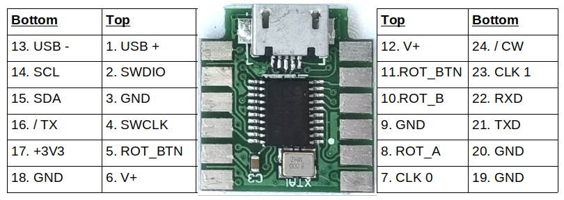
DigiVFO is a miniature but highly functional VFO using the MS5351M synthesized clock generator, and is based on the ProgRock2 module already produced by QRP Labs. Different firmware, and the addition of a standard rotary encoder and 0.91” I2C OLED module, facilitate the DigiVFO: A feature-rich VFO with BFO and CAT control USB interface. |

The features of this kit are as follows:
- Tiny size PCB, a little smaller than an HC6 crystal: 0.725 x 0.675 inches (18.4 x 17.1mm)
- Factory assembled PCB, ready-to-use: assembly is just connection of the rotary encoder and OLED module.
- 0.25ppm TCXO reference as standard; typical drift and accuracy will be less than 1Hz at 40m band, for example.
- Output frequency range is configured to cover 1.000000 MHz to 99.999999 MHz.
- Supports direct conversion receivers, including with 90-degree quadrature phase LO
- Supports superhet with low-side or high-side LO injection
- For superhet radios, also generates the BFO with configurable frequency
- Configurable CW receive offset (CW or CW-R), if you ground an input pin to indicate you are in CW mode
- RIT (Receive Incremental Tuning)
- VFO A / B / Split mode
- CAT control interface via built-in USB to Virtual COM Serial port (USB-C connector)
- CAT via separate USART port for 3.3V logic level serial (e.g. other microcontroller)
- QRP Labs Firmware Update (QFU) bootloader for firmware updates
Assembly is simple. The rotary encoder is soldered directly to pads on the PCB, which is hardly larger than the rotary encoder itself. 4 wires connect the OLED.
DigiVFO can be used in multiple ways. It can be used as the VFO and BFO of a superhet (BFO frequency is configurable). Or just the VFO. Or use it as the VFO of a Direct Conversion receiver. It even has quadrature output (90-degree phase shifted outputs on two output pins) to directly drive a Quadrature Sampling Detector type mixer (a.k.a. Tayloe Detector). CAT control via the built-in USB Virtual COM Serial port makes it easy to interface with PC software; CAT commands can also be issued by a microcontroller host via the onboard USART port.
NOTE: Rev 3 PCB has a USB-C connector. Earlier PCB revisions 1 & 2 have a USB-Micro connector.
Kit contents
- PCB (same PCB is used for ProgRock2 and DigiVFO).
- Rotary encoder.
- 0.91" OLED display module.
- 50cm of 0.33mm enameled copper wire for connecting PCB to OLED.
Documents and resources
Manual - firmware version 1.00/1.01/1.02 (released 20-Dec-2025)
Firmware version history
Please refer to the manual for the firmware update procedure, which is very easy and does not require any special hardware, software, drivers etc. It requires only a PC and a USB cable. Click the file in the first column of the table below, to download the firmware file of interest. Note that firmware files are encrypted and can only be used on the QRP Labs ProgRock2/DigiVFO board.
Firmware version history:
| Version | Date | Contents |
| 1_02 | 07-Jan-2026 | Bug fix: BFO output initialization |
| 1_01 | 30-Dec-2025 | Bug fix: output frequency bug |
| 1_00 | 20-Dec-2025 | First firmware version |
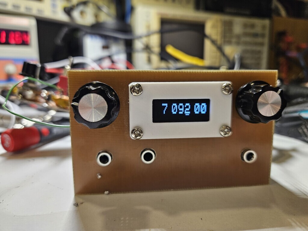
Photographs


LARCset connections
Replacing the analog VFO in LARCset is a simple matter disconnecting the inductor L1 from the junction of C3 and C60; then connect the Clk0 output of DigiVFO there directly. With the original LC analog VFO the waveform at the T1 coil (Q3 collector) is about 1.5V peak-peak and nice and symmetric. With the DigiVFO it is almost the same, just a bit more square, which will be a slight improvement as far as the mixer performance is concerned.
The same also applies to the BFO. Simply disconnect the crystal Y1 and connect the DigiVFO Clk1 output in its place. With the original crystal oscillator BFO the waveform at the T3 coil is about 1.5Vpp and quite asymmetric. With the DigiVFO substituted the amplitude is the same but the waveform is much more symmetric - meaning more square - which will improve mixer performance.
It is best to use a piece of shielded cable or twisted pair, to connect Clk0 + Ground to the VFO input, and Clk1 + Ground to the BFO input. Don't just rely on ordinary ground connection somewhere, which is fine for DC but not for RF. Take the Ground along with the signal.
DigiVFO needs a supply voltage at its V+ pin. Read the DigiVFO for more information on this. A 7805 or 78L05 voltage regulator works fine; the DigiVFO can tolerate supply voltages up to 12V but the onboard voltage regulator heat dissipation will be too high in that case. It is better to use a lower supply voltage; or perhaps an appropriate resistor to reduce the voltage down to say 6-9V.
These are the appropriate DigiVFO settings to use with LARCset, check the configuration menu of DigiVFO and make adjustments if necessary:
- TYPE: LOW
- BFO: 11 059 200 (or adjust to whatever places it best relative to the IF filter)
- START: 7 100 000 (set it to whatever you want the radio to be at power-up)
- CW OFFSET: 700 (I actually measured the sinewave osc on my LARCset as 675 Hz - so match it to that ideally)
- CW R: YES (because LARCset operates in Lower sideband mode, even when sending CW)
- CW TONE: YES (because LARCset generates CW by injecting an audio sinewave tone)
This is a nice 0.91" OLED bezel design, that will let you make a tidy front panel:
https://www.thingiverse.com/thing:5195272
The bezel has the big advantage that you don't have to face the horrendous task of drilling a rectangular opening in the front panel. All you need is 4 holes for the screws and a hole for the wires.