|
|
QCX-mini: a feature-packed, high performance, single-band 5W CW transceiver kit, with WSPR beacon and built-in alignment/test equipment. Available for 160, 80, 60, 40, 30, 20 or 17m bands. It has rotary encoder synthesised tuning, VFO A/B/Split, Iambic keyer, CW decoder, and more... |

The "QCX-mini" (QRP Labs Xcvr - mini): a feature-packed, high performance, single band 5W CW transceiver kit with WSPR beacon and built-in alignment and test equipment. It is designed specifically for portable operations where small size, weight and current consumption are all important (see Special portable-friendly features section, below). Available for 160, 80, 60, 40, 30, 20 or 17m bands. Experimental use on 15, 12, 10 or 6m (lower power output and reduced sensitivity).
QCX-mini is available either as a KIT or as an Assembled/Tested/Adjusted transceiver: CLICK HERE
The yellow/green LCD has a backlight which can be switched on/off via the menu system or double-clicking the rotary encoder shaft button. This provides current consumption savings; furthermore, low-current operational amplifier ICs have been used, resulting in a Receive current of only 58mA (12V supply, backlight off). The LCD is daylight and even SUNLIGHT readable without the backlight.
The Optional enclosure is black anodized extruded aluminium, very sturdy and elegant. The enclosure size is 95 x 63 x 25mm without protrusions. The top and side panels are drilled and cut to match the QCX-mini with laser-etched lettering. The enclosure includes four self-adhesive feet.
Special portable-friendly features:
- Small size: 95 x 63 x 25mm enclosure (plus protusions)
- Low current consumption (for example 58mA receive current, with 12V supply and display backlight off)
- Low weight, 202 grams
- Sturdy extruded aluminium enclousre
- All-metal BNC short connector, bolted to enclosure
List of features:
- Easy to build, two-board design, board with main circuit and connectors, display panel board with LCD; all-controls board-mounted on a press-out sub-board. No wiring, all controls and connectors are board-mounted
- Professional quality double-sided, through-hole plated, silk-screen printed PCBs
- Choice of single band, 160, 80, 60, 40, 30, 20 or 17m
- Approximately 3-5W CW output (depending on supply voltage)
- 7-14V recommended supply voltage
- Class E power amplifier, transistors run cool…
- 7-element Low Pass Filter ensures regulatory compliance
- CW envelope shaping to remove key clicks
- High performance receiver with at least 50dB of unwanted sideband cancellation
- 200Hz CW filter with no ringing
- Si5351A Synthesized VFO with rotary encoder tuning
- 16 x 2 yellow/green LCD screen
- Iambic keyer or straight key option included in the firmware
- Simple Digital Signal Processing assisted CW decoder, displayed real-time on-screen
- On-screen S-meter
- On-screen real time clock (not battery backed up)
- Full or semi QSK operation using fast solid-state transmit/receive switching
- Frequency presets, VFO A/B Split operation, RIT, configurable CW Offset
- Configurable sidetone frequency and volume
- Connectors: 2.1mm power barrel connector, 3.5mm keyer jack, 3.5mm stereo earphone jack, 3.5mm stereo jack for PTT, 3.5mm stereo jack for CAT control, BNC RF output
- Built-in test signal generator and alignment tools to complete simple set-up adjustments
- Built-in test equipment: voltmeter, RF power meter, frequency counter, signal generator
- Beacon mode, supporting automatic CW, FSKCW or WSPR operation
- GPS interface for reference frequency calibration and time-keeping (for WSPR beacon)
- CAT control interface
- Optional 50W PA kit
- Optional aluminium extruded cut/drilled/laser-etched black anodized enclosure
Documentation
Assembly manual for PCB Rev 3 (document version 1.13 published 14-Mar-2023)
Assembly manual for PCB Rev 1 & 2 - for Rev 2 see notes below (document version 1.05 published 15-Dec-2020)
Operating manual for firmware 1.08/1.09
Assembly manual, French translation (of doc rev 1.05 by Tim Fidler in ZL (26-Jan-2021)
Hi-Res schematic for display and controls PCB (QCX-mini Rev 3)
Hi-Res schematic for main PCB (QCX-mini Rev 3)
IMPORTANT notes for PCB Rev 2 (not contained in manual):
- The voltage regulator has been changed to 78M05 (previously AMS1117); the 78M05 is larger and more robust.
- Components near the voltage regulator (D33, C21 and C22) have been repositioned slightly to make room for the larger voltage regulator. It is easy to see where they should be installed, following the silkscreen print on the PCB; make sure D33 is correctly orientated - the white stripe end of D33 should be in the hole nearest the PCB edge.
- Step 3.42, the addition of an 10uF electrolytic or tantalum capacitor in parallel with C38, is neither required nor recommended on a Rev 2 PCB; the existing C38 capacitor is properly rated and is perfectly adequate. Therefore ignore step 3.42.
Troubleshooting
- There is an extensive QCX troubleshooting guide, click here
- An excellent article on troubleshooting 60 QCX-series kits, by Ron WA7GIL, see here
- There is a detailed video about QCX troubleshooting, click here
Photographs
QCX-mini in its beautiful black-anodized extruded aluminium enclosure, CNC machined to suit the QCX-mini and with durable laser-etched lettering:


The PCBs inside:


QCX-mini undergoing testing in bright Mediterranean sunshine conditions, on the occasion of several visiting YL's wearing sunglasses, who were persuaded to part temporarily with their precious accessories:


Comparisons of the QCX-mini, QCX+ and original QCX (in the folded aluminium BaMaTech enclosure).


ARRL Review of QCX-mini in November 2021 QST issue
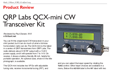
Paul N1II reviewed the QCX-mini transceiver in the November 2021 issue of the ARRL monthly publication QST.
CLICK HERE to read the PDF (333K file)
Reproduced with the permission of the ARRL. Copyright ARRL.
Visit the ARRL website here.
QCX-mini introductory VIDEO
QRP Labs' YouTube channel video introducing QCX-mini: http://www.youtube.com/v/VET_JgxCwxw&t&list
Why QCX-mini?
QCX-mini is a response to quite a few comments on the new QCX+ kit, from people who want to take it out portable for SOTA operations and other portable operations, and complained that the QCX+ is bigger and that they preferred both the smaller size, and the format (controls and display on the top face) of the original classic QCX. Generally speaking, QCX-mini is not an experimenters radio; there is not a lot of spare space inside the enclosure and most of the circuit is SMD. QCX-mini is a specalised design for minimum size, intended for portable operations.
QCX-mini uses basically the same schematic as the QCX+ and the same firmware chip. Operation and performance are the same. This is NOT therefore being undertaken as a large, time-consuming project. Specifically, the scope is restricted to keeping it QCX-compatible, to minimize development time. Just make-it-smaller. The project therefore is a mechanical re-engineering task, with some documentation towards the end, and a small firmware change to facilitate the configurable LCD backlight.
QCX-mini compared to QCX and QCX+
QCX-mini has almost the same circuit (schematic) as QCX and QCX+. It also uses the same firmware chip, in the same 28-pin DIP package. The operating characteristics and performance are also the same. QCX-mini has the same connections as QCX+, even including the CAT and PTT connectors. The primary difference and motivation is to make it smaller. The following table is a comparison with the QCX installed in a BaMaTech aluminium enclosure. All dimensions are excluding protrusions (controls and connectors).
| Radio | Dimensions (cm) | Dimensions (inches) | Volume (cm3) | Volume (inches3) |
| Classic QCX | 11.2 x 9.4 x 3.5 | 4.4 x 3.7 x 1.4 | 368 | 22.5 |
| QCX+ | 10.6 x 5.5 x 14.7 | 4.2 x 2.2 x 5.8 | 854 | 52.1 |
| QCX-mini | 9.5 x 6.3 x 2.5 | 3.7 x 2.5 x 1.0 | 150 | 9.1 |
It can therefore be seen that while QCX+ is 2.3 times larger than QCX by volume, QCX-mini is 2.5x smaller than QCX by volume. QCX-mini is 5.7x smaller by volume, than QCX+.
The dimensions for QCX-mini assume installation in the optional aluminium enclosure, which will be the same aluminium extrusion profile as the 50W PA kit, but cut shorter (92mm) and of course drilled and laser-etched differently.
QCX-mini has the following changes, to implement the smaller size and other features:
- Extensive use of 0603-sized SMD components, which will be factory pre-assembled. The inductors are still toroids and the NP0 capacitors in the RF section are still through-hole type, the same as in QCX+. The BS170 and MPS751 transistors are also still through-hole and bolted to the PCB by a nut, bolt and washer just like on the QCX+
- Yellow/green LCD which is highly readable outdoors, and readable without the backlight (to reduce current consumption). This is the same high quality LCD made by the QY brand, as used in all QRP Labs kits; it has two backlight LEDs rather than the usual single LED found on cheaper LCDs. Since the LCD is the same size and style as the original QCX/QCX+ kits, it offers the same easy to read, large text.
- Smaller gain (volume) potentiometer
- Multi-PCB sandwich assembly, designed to slide into an optional aluminium enclosure
- Smaller, all metal, high quality, robust BNC connector
- Lower current op-amps for ICs 6, 7, 8, 9 and 10 to reduce overall power consumption
Additionally the QCX-mini is compatible with the TCXO module option designed for the QCX+.
Although it is very compact, QCX-mini is faster and not more difficult to build than the QCX+. The circuit is basically the same but many of the components are SMD and are already factory-installed. That leaves the coils to wind and install, the NP0 capacitors of the RF section, the connectors, controls, IC sockets and a few other through-hole components.
Weight comparison
| QCX model | Weight (g) | Weight (ounces) |
| QCX-mini | 202 | 7.1 |
| QCX ** | 288 | 10.2 |
| QCX+ | 559 | 19.7 |
** Note: QCX in BaMaTech enclosure
Current consumption
| QCX model | Supply voltage | LCD backlight | Current consumption |
| QCX-mini | 12 | OFF | 58 mA |
| QCX-mini | 12 | ON | 72 mA |
| QCX-mini | 13.8 | OFF | 58 mA |
| QCX-mini | 13.8 | ON | 76 mA |
| QCX | 12 | ON | 112mA |
| QCX | 13.8 | ON | 118mA |
| QCX+ | 12 | ON | 112mA |
| QCX+ | 13.8 | ON | 118mA |
QCX-mini development VIDEO
I discussed the QCX-mini development in a live video recording Q&A Zoom session recently, as part of QRP Labs participation in the QSO Today Virtual Ham Expo.
QCX-mini Development updates
The following sub-pages were published during the development of the QCX-mini kit and provide insights into the development.
Dev Update 1: 11-Sep-2020
Prototype boards arrived! Some preliminary assembly was possible with parts on hand, enough to verify the boards fit together properly and boot up the QCX, operate the Si5351A and do some testing on the visibility of the display in outdoor conditions. This article also explains more about how the QCX-mini boards fit together etc. READ MORE...
Dev Update 2: 24-Sep-2020
SMD components arrived on Monday 21-Sep-2020 and two prototypes have been assembled, debugged, tested and adjusted. The first QSO with the QCX-mini was with Feri HA2EOU on 24-Sep-2020. READ MORE...
Dev Update 3: 25-Sep-2020
The enclosure prototype was delivered on Thursday evening 24-Sep-2020 and I was excited to see that everything fit perfectly as I had planned it. I also made a weight comparison and current consumption comparison. READ MORE...
Dev Update 4: 28-Sep-2020
This article details work to resolve the microphony problem. I am comfortable that the problem is solved and the next step is to redesign the PCB to accommodate the changes. READ MORE...
Dev Update 5: 30-Sep-2020
QCX-mini development phase is complete! QCX-mini has now entered the kit manufacturing phase! READ MORE...
Dev Update 6: 16-Nov-2020
Good news at last... after several unexpected delays, all component sourcing, custom-component manufacture, PCB and SMD Assembly steps are now completed! Next is shipping to me!READ MORE...
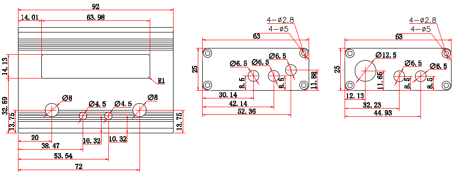
Drilling templates for QCX-mini enclosure
Drawing is provided for personal use only for example for a personal 3D-printing project. Drawing is copyright QRP Labs and may not be reproduced, used for production etc.
SOTA station by Berni G0IDA
Berni sent in this photograph of his complete SOTA station fitting in a 8.5" x 7" shell case.

SOTA station by Jim KC0DGR
Jim sent in this photograph of his SOTA station "I have attached a photo to show how a QCX-Mini, CW Key, Battery, Clock and Log Sheet can all fit on an 8 1/2 x 11 in dry-erase board. It works great for SOTA"

Portable QCX-mini station by Viktor UT3URA
"I made a secure "go-box" for QCX (Maybe you'll like it). A very small case with protection in which I placed everything (and a 20-meter antenna and a mini key)"... GREAT work Viktor!


