Dev Update 30-Sep-2020
QCX-mini development phase is complete.
QCX-mini has now entered the kit manufacturing phase!
There were a total of 18 board changes implemented, one of which was replacement of the 9 microphonic SMD capacitors with through-hole equivalents.
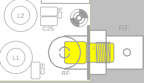
SMA RF output
Several people requested including a footprint for an SMA connector, within the same footprint area as the BNC connector on the board.
I have implemented this request, using a 90-degree PCB mounting SMA connector with a standard footprint which should be easy to obtain (it will not be included in the kit). This will protrude through the same enclosure hole as the intended (supplied) BNC connector. I am not quite convinced that it would protrude far enough from the PCB edge, once the 1.5mm enclosure wall is in place; but I cannot move it any close to the PCB edge or the drill holes will be too close to the edge. So this will have to be treated as a somewhat experimental feature for now.
Microphonic capacitors replacement
The nine microphonic SMD capacitors discussed at length in update 4 were replaced with equivalent through-hole capacitors. These are indicated in RED in the following diagram. Squeezing them in and re-routing the traces was very tough!
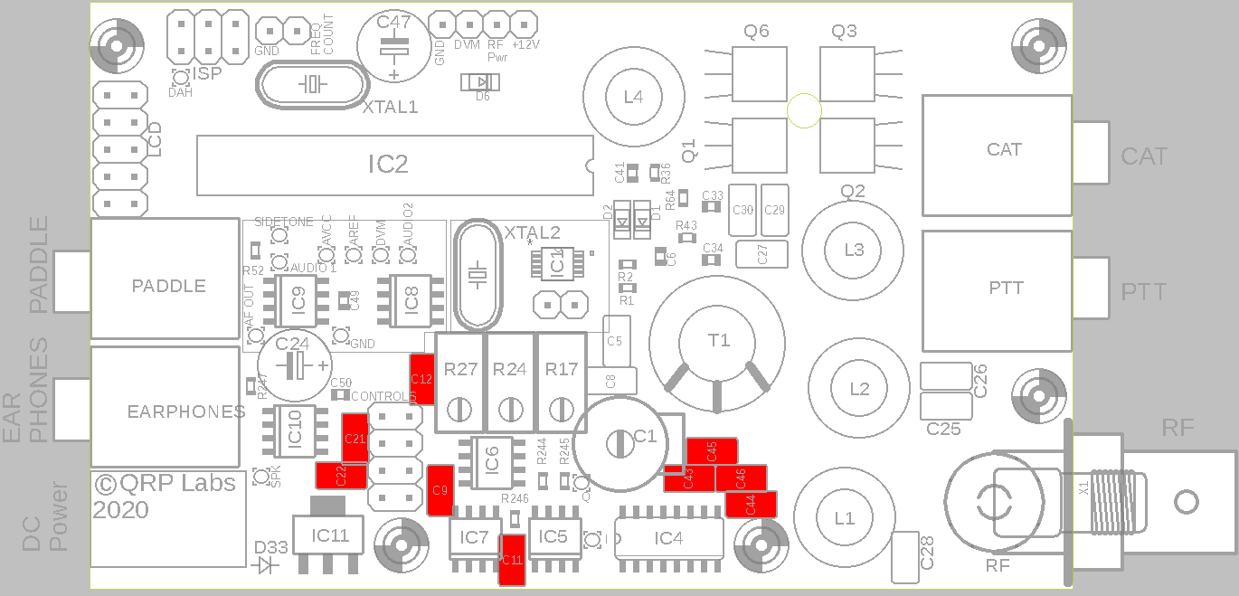
Final PCB layout diagrams
Click the thumbnails below to see the component layout on each of the two boards; as detailed in previous updates, the top PCB (PCB #1) has several pop-out boards, most important of which is the Controls PCB, that holds the volume and rotary encoder and the two buttons. This small PCB is fit into the cut-out for the LCD module.


Next...
Next is the kit preparation stage, there are many tasks:
- Component sourcing
- Manufacturing and populating the PCBs
- Kit packing
- Firmware (Finalize modification for the LCD backlight control)
- Documentation (manual)
- Web site and shop
This will take maybe 4 weeks.