|
|
QCX+: a feature-packed, high performance, single-band 5W CW transceiver kit, with WSPR beacon and built-in alignment/test equipment. Available for 160, 80, 60, 40, 30, 20 or 17m bands. It has rotary encoder synthesised tuning, VFO A/B/Split, Iambic keyer, CW decoder, and more... |

The QCX+ features the same circuit, same firmware and same operational characteristics as the amazingly popular QCX transceiver launched in August 2017. It is a 5W, single-band, high performance CW transceiver kit with WSPR beacon, and built-in alignment/test equipment. It is available for 160, 80, 60, 40, 30, 20 or 17m bands. See below for the long list of features! This is a kit of parts that you assemble yourself. There are NO surface mount components to solder (two SMD ICs are already factory pre-soldered).
QCX+ is available either as a KIT or as an Assembled/Tested/Adjusted transceiver: CLICK HERE
There is also a smart extruded anodized aluminium enclosure available, with laser-etched text and holes cut to fit the QCX+.
Please see QCX Frequently Asked Questions page for any queries you have. In case of any problems, please see the QCX trouble-shooting page.
Features
- Easy to build, spacious 13 x 10cm main board, separate front panel board with all controls board-mounted
- Professional quality double-sided, through-hole plated, silk-screen printed PCBs
- Choice of single band, 160, 80, 60, 40, 30, 20 or 17m
- Approximately 3-5W CW output (depending on supply voltage)
- 7-16V recommended supply voltage
- Class E power amplifier, transistors are bolted to the PCB as a heatsink, though heat dissipation is minimal
- 7-element Low Pass Filter ensures regulatory compliance
- CW envelope shaping to remove key clicks
- High performance receiver with at least 50dB of unwanted sideband cancellation
- 200Hz CW filter with no ringing
- Si5351A Synthesized VFO with rotary encoder tuning
- 16 x 2 blue backlight LCD screen
- Iambic keyer or straight key option included in the firmware
- Simple Digital Signal Processing assisted CW decoder, displayed real-time on-screen
- On-screen S-meter
- Full or semi QSK operation using fast solid-state transmit/receive switching
- Frequency presets, VFO A/B Split operation, RIT, configurable CW Offset
- Configurable sidetone frequency and volume
- Connectors: 2.1mm power barrel connector, 3.5mm keyer jack, 3.5mm stereo earphone jack, 3.5mm stereo jack for PTT, 3.5mm stereo jack for CAT control, BNC RF output
- Built-in test signal generator and alignment tools to complete simple set-up adjustments
- Built-in test equipment: voltmeter, RF power meter, frequency counter, signal generator
- Beacon mode, supporting automatic CW or WSPR operation
- GPS interface for reference frequency calibration and time-keeping (for WSPR beacon)
- CAT control serial data interface
- Optional 50W PA kit
- Optional Enclosure
- Optional TCXO module
- Optional Dev kit
Assembly and operating instructions
Make sure you have the correct assembly manual for your PCB revision (PCB revision is printed on the front left corner of the main rear PCB of the QCX+).
Assembly manual for PCB Rev 4 - CLICK HERE (document revision 1.14, 03-May-2026)
Operating instructions - CLICK HERE (firmware version 1.07, 02-Dec-2020)
Other documents:
Assembly manual for PCB Rev 3 - CLICK HERE (document revision 1.07, 14-Feb-2022)
Assembly manual for PCB Rev 1 & 2 - CLICK HERE (document revision 1.04, 02-Nov-2020)
Old Manual - CLICK HERE - includes firmware operating instructions for firmware version 1.05. (document revision 1.03, 06-Aug-2020)
Japanese Manual Part 1 (document revision 1.04, thanks to Max JK1EDS for the translation)
Japanese Manual Part 2 (document revision 1.04, thanks to Max JK1EDS for the translation)
Japanese Operating instructions (version 1.07, thanks to Max JK1EDS for the translation)
Manual GERMAN TRANSLATION - CLICK HERE (document revision 1.03, 12-Aug-2020) - thanks Ben DK5FN
Older firmware version manuals are on the firmware version history page.
High resolution black/white schematics:
Rear PCB image CLICK HERE
Front PCB image CLICK HERE
Both PCBs embedded in printable PDF CLICK HERE
Firmware
The QCX/QCX+ firmware has undergone a continuous process of improvement, to add new features requested by QCX owners, since August 2017. If you have an AVR programmer you can update your firmware using the on-board programming header. The firmware version history and more information are on this page (click!).
QCX+ vs QCX - what are the differences, and new features of QCX+?
The QCX+ is the almost same circuit as the QCX, with two very minor changes. QCX+ runs the same firmware as QCX, and has identical operational and performance characteristics. QCX/QCX+ firmware will always be compatible with both the QCX and QCX+. The evolution of QCX to QCX+ provides several improved features in physical layout, as follows:
1) Physical layout of controls and connectors
QCX was a single board design, with all connectors and controls board-mounted. It was somewhat inconvenient to fit the board into an enclosure, since connectors were on the left and right sides, while the controls and LCD were all at different heights to the PCB.
In contrast, QCX+ is a two-board design with a conventional desk-top style vertical front panel carrying the LCD and controls; this vertical faux front panel PCB plugs into a horizontal PCB behind that contains the majority of the circuit. All the connectors are on the rear edge of the PCB making it much easier to fit the PCB into an enclosure.
An important addition in QCX+ is the locking push-switch on/off button on the front panel (bottom left).


2) Optional enclosure
No official QRP Labs enclosure was available for QCX, though BaMaTech created a nice aluminium enclosure, several 3D printed designs were published and even sold, and many constructors showed great creativity in producing beautiful enclosures for their QCX kits.
QCX+ is specifically designed to fit a custom-manufactured black anodized aluminium enclosure measuring 106mm wide by 55mm high and 146mm deep. The enclosure is supplied with four self-adhesive feet. It is laser-etched and cut and drilled to match the QCX+ PCB.
The main QCX+ PCB slides into the extruded aluminium enclosure body along PCB mounting grooves at the sides of the aluminium extrusion.
3) Additional and changed connectors
QCX+ features a 2.1mm barrel power connector for DC power input (compared to the two screw terminals on QCX); the QCX+ transceiver also has two additional 3.5mm stereo jack socket connectors, for PTT (to fit the QRP Labs 50W QCX amplifier) and CAT control 38400 baud serial port.

4) More spacious PCB, more than double the board area, with less densely packed components, and more test/modification points
QCX was on a single 10 x 8cm PCB. The main PCB in QCX+ is 13 x 10cm, which is a 63% increase in board area, and additionally the controls and LCD are moved off onto their own front panel PCB. Together with the front panel, in total the area of QCX+ PCBs are more than 2.2x that of the QCX PCB. This increase in space means that the assembly of QCX+ is easier, because component density is lower.
- All QCX+ PCB traces are 16 mil (thicker traces than the 12 mil size used in QCX).
- All resistors, diodes and inductors that were mounted vertically in QCX, are now laying horizontally in QCX+
- There are numerous test points at the input and output of each stage of QCX+, and these can also be used to connect other circuits when making modifications to your QCX+ or experimenting
- Four mounting holes near the corners of the main PCB, together with the large amount of space in the QCX+ enclosure, make it possible to add further PCBs experimentally as you wish, for example a battery compartment etc.


5) Improved heatsinking
Or I should say - heatsinking - since the QCX had none! In QCX+, the three BS170 PA transistors and the MPS751 keying envelope shaping transistors, are bolted with their flat faces directly on an exposed copper pad on the PCB, this provides some heatsinking. Additionally the 7805 is now at the rear edge of the PCB where it may be bolted to the enclosure, for example when using the official QRP Labs enclosure.


6) Three minor circuit changes
Aside from the two additional connectors, and the locking push-button on/off switch, there are also three more minor circuit changes in QCX+:
- An additional 0.1uF supply decoupling capacitor has been added, for even better supply decoupling
- C24 has been increased from 10uF to 470uF, which further reduces the transmit/receive switchover click
- Additional 10K resistor from IC3 pin 13 to pin 14 as documented here http://qrp-labs.com/qcx/qcxmods/ptt.html
7) No microswitch key
The only loss in the QCX+, is no more microswitch key on the board... that just doesn't fit properly on a vertical front panel and main horizontal board, with the enclosure option etc.

ARRL Review of QCX in August 2019 QST issue
Paul N1II reviewed the QCX transceiver in the August 2019 issue of the ARRL monthly publication QST. Quoted performance for QCX+ is expected to be equivalent to QCX, since there are no component changes and great attention has been given to PCB layout in both QCX and QCX+.
CLICK HERE to read the PDF (497K file)
Reproduced with the permission of the ARRL. Copyright ARRL.
Visit the ARRL website here.
Videos and reviews of QCX
The original QCX kit was originally designed for the RSGB Youths On The Air summer camp buildathon in August 2017. This RSGB YOTA Vlog video, shot at QRP Labs booth at Friedrichshafen 2017.
For more videos and reviews please see the QCX videos page!

K9YA Telegraph, March 2018 edition, review by Philip K9PL
The K9YA Telegraph's March issue has an article on the QCX by Philip K9PL, sub-titled "QRP Labs Moves the Goalposts". Philip concludes his 3-page article: "...the QCX behaves like a monoband, QRP slice out of a QRO high-end rig with deep, deep menus - very innovative and a joy to operate.
The K9YA Telegraph is a free monthly Ham Radio eZine, see http://www.k9ya.org/ for details.
Philip K9PL has provided a PDF of the article with permission to reproduce it on the QRP Labs website. CLICK HERE to read it!
Troubleshooting
- There is an extensive QCX troubleshooting guide, click here
- An excellent article on troubleshooting 60 QCX-series kits, by Ron WA7GIL, see here
- There is a detailed video about QCX troubleshooting, click here
Phase noise measurements
For a detailed page about phase noise measurement techniques and the measurements on the QCX in particular, CLICK HERE.
The transmitter output phase noise measured was within 1dB of the -135 dBc/Hz at 10 kHz and 50 kHz spacing measured by ARRL in their QST review (see above). This level is considered GOOD. No improvements were found to get better phase noise performance from the QCX.
Performance measurements by Ed WA4MZS
Ed made some interesting measurements of his 40m QCX serial number 354 (see also builders' photos page).
- Power supply = 13.8 VDC
- Current draw (receive) = 123 mA
- Current draw (transmit) = 514 mA
- Transmitter output (50Ω load) @ 7.020 MHz = 4.0 watts
- Receiver MDS @ 7.020 MHz = -121 dBm (0.2 µV)
- Reference frequency = 27.004345 MHz
- Transmitter frequency (display 7.020 MHz) = 7.0200003 MHz
- Transmitter 2nd harmonic (14.040 MHz) = -48.74 dBc
Spectrum analyser close-in and wide screenshots:


Internal battery and antenna tuner by Douglas W0UHU


Adjustment screwdriver from scrap PCB by Axel DL5GT
The QCX+ PCBs often have a strip along one (or more) edges which is a remnant of the PCB manufacturing process, where the PCB's are made on larger panels. Axel used one of these pieces, suitably filed to a chisel shaped point, as a scewdriver for adjustment of the trimmer potentiometers. Useful idea for when you don't have a screwdriver the right size! Thanks Axel!

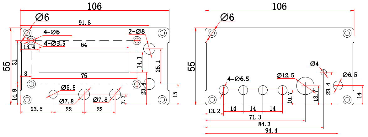
QCX+ Drilling template
Drawing is provided for personal use only for example for a personal 3D-printing project. Drawing is copyright QRP Labs and may not be reproduced, used for production etc.