UPDATE 18-Mar-2025: The QSX project is now officially cancelled. The QMX+ transceiver has grown to cover at least 95% of the QSX functionality and in many areas has higher performance and more features, and it does so at a lower price. The following announcement was made to the QRP Labs groups.io forum on 18-Mar-2025:
I hereby officially retire the QSX project http://qrp-labs.com/qsx which was started in 2018 and aimed to provide a low cost, high performance multi-band multi-mode QRP transceiver. QSX was an ambitious project, probably TOO ambitious. I did probably bite off more than I could chew. As a result of publicity around the project it also caused a lot of pressure and stress.
But things developed regardless; and it was a happy day when I decided to take a break from it, and put it on the shelf for a while while I continued with other developments. Numerous new kits came about including the QCX 50W PA, then the QCX+, QCX-mini, QDX, QMX and QMX+. Many people noticed and commented that many of these new kits took steps towards my original goals for QSX. I was getting there, step by step.
Now with the implementation of SSB and CESSB in QMX+, there is at least a 95% overlap between the planned functionality of QSX and the planned/delivered functionality of QMX+. In many ways QMX+ surpasses the QSX plan in features and performance, and does so at a lower price ($125 compared to my $150 target for QSX, both without enclosure).
I am measuring for example, IMD -40 dB PEP two-tone test results in QMX+ on 40m; that compares to -30 dB PEP measured on the 10W Linear module of a QSX, -35 dB PEP for Elecraft K3S (ARRL lab measurement in QST review) and -36 dB PEP for Elecraft KX2 (ARRL lab measurement in QST review). Of course two-tone testing isn't everything but as a single number comparison point, it's not a bad indication.
So we'll continue and focus on QMX/QMX+ firmware development. And consign QSX to history, with respect to the ambition, innovation and ongoing development which it inspired, and whose end result is now the QMX-series.
The rest of this page has not been altered and remains for information purposes.
QSX (QRP Labs SSB Xcvr) is a 40m SSB transceiver. It will have an optional 10-band (160m-10m) filter module, and an optional extruded aluminium enclosure. This will make an all-band HF all-mode 10W High performance transceiver.
The kit inherits all the functionality of the famous QCX single-band CW transceiver kit but adds SSB, AM, FM, PSK31 and RTTY. This will be the lowest cost all-HF radio available but also high performance and packed with features. These are the planned features of QSX:
- Software Defined Radio (SDR) technology with standalone Digital Signal Processing (DSP), no PC required
- Very high performance 24-bit Analog to Digital Converter (ADC) and 24-bit Digital to Analog Converter (DAC)
- 40m (single band); or with optional extra board, 160-10m (10-band, including 60m)
- Modes: SSB, CW, AM, FM, PSK31, RTTY, WSPR beacon
- Power output: 10W from 13.8V supply (power output is adjustable by the firmware)
- Single power supply needed, 12V to 14V
- USB host interface and connector, for USB keyboard to allow PC-less operation on PSK31 and RTTY
- USB device interface and connector, for PC CAT Control
- QSX can appear to a PC as a high performance 24-bit USB sound card and radio - for digital modes from a PC e.g. FT8, either demodulated or as I-Q for PC SDR programs
- Built-in CW IAMBIC keyer (or straight keying also possible) with raised-cosine key-envelope shaping
- DSP features (selectable sharp filters, AGC, Speech Compression, Noise Reduction etc.)
- Dual microphone inputs (mobile phone headset with VOX, or RJ45 connector for Kenwood/Yaesu mics)
- Dual VFO (A/B/Split), frequency and message memories
- Through-hole assembly only
- Built-in test equipment features for alignment, debugging and general purpose use
- Detailed assembly manual
- Macro facility for user defined sequences of operations, or redefinition of controls
- Front panel: 16 x 2 LCD (yellow/green backlight), 2 rotary encoders, 4 buttons, mic/earphones socket
- Soft-power on/off switch, the radio saves its state automatically on switch off, so that it starts up in the same state next time
- Free firmware updates for life, very simple firmware update procedure via a USB memory stic
QSX is still in development! The above list is subject to change. The following is a FAQ with information about QSX.
QSX FAQ
When will QSX be available?
We don't have an exact date, it depends how long it takes to finish all the above features and manufacture it etc. *Hopefully* something like November 2018, but this could change. Any updates will be published on this page.
Update July 2020: Please see http://qrp-labs.com/newsjul2020.html#c3
Update 20-Aug-2019: I know this is taking longer than expected, but there are still a number of details to sort out. I do not want to release it before it is properly ready. It needs to work perfectly first. It's a huge complex project... so please bear with me, patiently...
Update 25-Jan-2019: Development continues, progress is being made but there are a lot of details to take care of. Still no update on projected completion dates yet.
Update 05-Nov-2018: We have some delays due to poor health, see https://groups.io/g/QRPLabs/message/27851 - recovering nicely now so will make more progress soon and update on this page.
Can I pre-order?
No. We aren't taking pre-orders at this time. Previous experience has shown that taking pre-orders before the development is finished adds to the stress and administration workload. The effort is better spent focusing on finishing the development!
What's this about YOTA 2018?
The QSX (40m version) was constructed by the attendees of the Youngsters On The Air (YOTA) 2018 summercamp buildathon in South Africa in August 2018 (therefore technically, a wintercamp). The full set of features wasn't completed in time for the summercamp but will be made available to the attendees over the coming weeks as it is developed.
Can I be a beta-tester?
Thanks but we don't need any more beta testers at this time!
What about X, Y, Z feature, and when will QSX be available, when can I order it?
Email us. But questions will be answered only if they are not already handled by this FAQ page. This way, we can concentrate on the hard work of finishing the development.
What are the dimensions of QSX?
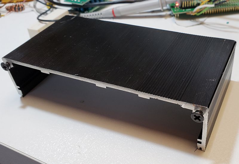
The extruded aluminium enclosure has external dimensions 145mm wide, 73mm deep and 68mm high. The knobs protrude 12mm from the front panel. Four self-adhesive rubber feet will be supplied for the bottom and these would add 5mm to the bottom if installed. Finally at the rear, the heatsink protrudes 25mm from the rear panel (as shown in the photos). You may need to make allowance for RF, Power etc connectors at the rear panel too, this will depend on your own installation.
How much will QSX cost?
We aren't sure exactly yet. It is expected to be somewhere in the region of $75 or the 40m single-band version. Addition of the 10-band filter module and the anodized black aluminium enclosure should take it to around $150 in total. These are ballpark figures and subject to change.
How will firmware updates be installed?
QSX firmware updates will always be free for life. The firmware update procedure is very simple. No special hardware or software is required! Just copy the firmware file (with .QSX suffix) onto a USB memory stick, plug it in the back of the QSX, and select the firmware upgrade option in the Setup menu. The crypto bootloader we developed installs the new firmware in Flash memory.
Is the firmware Open Source?
In common with other QRP Labs projects, QSX firmware is not open source. It's sometimes a contentious issue for debate, and we are aware of the pro's and con's. For now we have taken the decision to NOT publish the source code.
In the event that support for QSX is ever discontinued, we pledge that the source code will be released to the amateur radio community. No abandonware!
Can the QSX operate as a general-coverage receiver?
The local oscillator will provide general coverage from 1.8MHz to 30MHz.
There are 10 quite narrow filters, the same design as the BPF kits http://qrp-labs.com/bpfkit . For general coverage reception, between the ham bands, there would be some attenuation because of being away from the filter center frequency. Another possibility is bypass the filter (which is also an option) - in that case, the Receiver would be open with NO band-pass filtering. The LOW PASS filter (Transmitter harmonic output) of the next higher ham band would still be in circuit, this provides some useful filtering and in particular it is necessary to remove the response of the Quadrature Sampling Detector down-converter, to the odd harmonics (3rd, 5th, 7th etc).
So the answer is yes - general coverage will be available - and AM is one of the modes supported; however the performance of the transceiver is optimized for ham bands; there is not a continuously-tunable variable frequency pre-selector band pass filter which can be independently adjusted to any desired general coverage reception frequency.
What are the performance specifications?
QSX is designed to have high performance, and be compliant with all regulatory requirements such as FCC regulations on spurious emissions. Exact specifications will come later.
 What space is available in the case for my own additional modules?
This diagram is drawn reasonably to scale and illustrates the side-view diagram of the QSX PCB assembly within the optional extruded aluminium enclosure. The enclosure consists of 4 parts:
- Cut, drilled, silk-screen printed front panel
- Cut, drilled, silk-screen printed rear panel
- Top U-shape extrusion
- Bottom U-shape extrusion
The top and bottom extrusions are identical. They have an I-tooth on one side and a U-groove on the other, so that when orientated correctly they slot together neatly. In the corner there is a shaped section which is tapped to accept screws which bolt the front and rear panels to the top/bottom extrusions. Each of the identical top/bottom extrusions has a PCB slot. The lower half slot is occupied by the rear QSX PCB. There are no holes drilled in the top or bottom panels. The assembly is held together by the corner bolts in the front/rear panels.
In the photo (right) note that the shiny metal cross-section is only visible because the enclosure was cut from an extrusion sample by me... in the final thing, the cross-section will of course, be anodized black like the rest of the enclosure.
The QSX front PCB is bolted in the corners and center of the enclosure front panel via spacers. Additionally it is bolted to the LCD module via shorter spacers. Therefore the front panel is fixed to the front (vertical) QCX PCB in 10 places and it is extremely secure.
The rear panel is fixed to the horizontal QCX PCB by the nut of the BNC connector, and by the 7805 voltage regulator tab bolted to the heatsink through the panel. Furthermore, the rear panel is sandwiched between the Linear PA PCB and the heatsink. The Linear PA PCB is bolted to the heatsink in three places (two PA final transistors, and the Driver transistor assembly). There is an additional bolt at the opposite end of the heatsink which just bolts the heatsink to the front panel at that end. The rear panel assembly is therefore also extremely secure and rigid.
Access of the top compartment is by removal of the 4 panel screws at the top two corners of the front and rear panels. respectively. Since the main horizontal PCB is slotted into the PCB slot of the lower half extrusion, the lower compartment cannot be accessed in this way.
To access the lower compartment it is necessary to remove all 8 panel screws, and gently prise apart the whole assembly, separating it at the board interconnectors between the front vertical and main horizontal PCBs. The recommended way to do this is with a thumb on each side, applying equal pressure to both left and right side, pushing it forward out of the enclosure; this avoids damage to the board interconnectors. When opened this way, the front PCB remains bolted to the front panel and has been separated from the rest of the radio; the main horizontal PCB remains fixed to the PA PCB and the Rear panel and can now slide out of the enclosure rails as a unit.
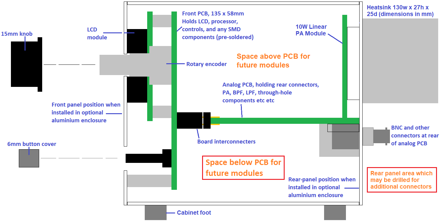 On the diagram (right - please click it to open a full-size image) you will note an area above the main horizontal PCB for future modules, and an area below the main horizontal PCB for future modules. The entire top half of the rear panel is entirely occupied by the large heatsink of the 10W PA module. The lower center region of the rear panel is occupied by the QSX connectors: RJ45 mic connector, 3.5mm paddle jack, RF BNC output, USB A (host) connector, USB B (device) connector, 2.1mm Power jack. There IS blank space at the bottom of the rear panel, where you could install your own supplementary connectors.
The area above the main horizontal PCB is expected to be used by the optional 10-band filter module, which is expected to occupy two PCBs stacked in the upper compartment.
The area below the rear hrizontal PCB would be the best place for your own modules. There is no current plan for any QRP Labs module that occupies this space, and also there is blank rear panel space where you could drill to fit your own additional connectors. The diagram does NOT show components protruding from the PCBs. No components are fitted protruding down below the QSX main horizontal PCB. Very approximately, the volume of free space below the PCB is about 130mm left-to-right by 42mm front-to-back by 25mm high. More than this is available in some places where connectors, enclosure extrusions, components etc do not block the way.
Since a Raspberry Pi Zero is sized 65 x 30mm, there would be plenty of space for a Pi Zero, and any potential shielding if it is found to be necessary.
Two sets of header pins are available on the rear QSX PCB, each provides Ground, an I2C bus and an asynchronous serial communication port. One has a pin for +3.3V and the other has a pin for +5.0V. If your device draws significant current you should probably provide your own supply voltage regulator arrangement.
CLICK HERE or the diagram to open a full-size image version!
QSX Photos
Here are some photos of the QSX transceiver (40m single-band version) in the prototype extruded aluminium enclosure. Since I cut the rectangle and button holes and screw holes by hand, the precision isn't very good. The final manufactured version with factory cut and silkscreen printed front and rear panels will look nicer. There are currently three boards: the front panel board, rear board, and PA board.


PA Photos
These photos show the PA Board, first revision. This 10W HF Linear PA module is now available separately for sale, see http://qrp-labs.com/linear.


YOTA 2018 buildathon photos
These pictures show some of the 2018 Youngsters On The Air summercamp happily working on their kit. YOTA 2018 summercamp was hosted by SARL in Johannesburg, South Africa. The buildathon day in South Africa was 12-Aug-2018. Finishing the kit in the allocated time was always going to be impossible. Some constructors could not be dragged away from their workbench. I went to sleep at 1am, leaving 12 people still soldering in the conference room. There were still some pictures of people continuing until 3:30am and I heard that a few did not sleep at all that night! So, some finished it; others continued in spare time on subsequent days; others took it home to finish gradually at their own pace. All participants were given the choice of three QRP Labs kits: Clock kit or Ultimate3S kit for 20m or QSX kit, in ascending levels of difficulty. By far the most popular choice was the QSX.


Faith Hannah AE4FH interviews QSX designer Hans G0UPL at YOTA 2018
QRP Labs YouTube channel videos
QSX's built-in spectrum analyzer with tracking generator feature, for aligning the Band Pass filters
Firmware updates, and the soft-power switch