 On September 4th at approximately 12:08 UTC a neoprene balloon that was designed for hoisting pennants at a car lot was launched lifting the usual U3 configuration, a 46' vertical dipole antenna attached to the balloon and and solar panel glued to the top of the U3 in a foam box at the feed point of the antenna. This time an 18" recovery parachute constructed from a light duty garbage bag was attached by a separate piece of dyneema fishing line to the top of the antenna where the balloon was connected. The hope was that after the balloon burst the weight of the U3 would be supported by the parachute and kept in the vertical position. This of course would not work well at high altitude where there was no air density to support the parachute. The payload, which included parachute and heavier 240mAh LiPo battery was 45gm.
The balloon weighed about 200gms and was designed for a working diameter of 4 feet.
The balloon was inflated to about 31" diameter (this was checked, when inflating, by opening the sliding garage doors to 31" and seeing if the balloon would fit through). This diameter represented a fill volume of 0.26 cu meters. This fill volume should provide a free lift of about 44gms... much higher than the previous flight of foil balloons that had a free lift of 1.5gms. The reason for a high lift was to compensate for the continual leakage of rubber based balloons, which are leaking gas slowly all the time they are inflated. While filling the balloon a small spot was observed on the middle part of the balloon that was about 3/8" diameter. This spot was much thinner than the rest of the balloon envelope.
If I had inflated this balloon in the store and had seen this imperfection I would have not accepted it, but decided to use it anyway as I had no idea how this would affect the altitude performance, but suspected an early failure.
Although no burst diameter was indicated on this type of balloon I used a similar weight of weather balloon that was written up as a burst diameter of 8' to 9' which would correspond to a burst altitude of 25,000 to 29,000 meters above sea level. At a burst altitude of about 11,000 meters, backwards calculations made the actual burst diameter at about 52", greater than the working diameter of 48", but not my much... I believe the weak spot in the balloon played a big part in the early failure.
Telemetry.
The balloon settled into a ascent rate of about 800m/12 minute reporting period or 4,000m/hr which is about 220'/min climb rate... by comparison a climb rate of 500'/min is an acceptable cruise climb rate for a single engine aircraft. On the last GPS telemetry received, the climb rate had changed to about 1,000m/period or about 275'/minute.
The telemetry on the previous transatlantic flight showed that the internal temperature of foam box was always above freezing at a fixed height of 8,500 meters asl, except after the sun went down, but on this flight the temperature dropped quickly to below freezing at less than 8,000m asl. This low temperature inside the foam box may have been caused by the boost converter not doing as much work and creating as much heat as the previous flight. The lipo battery maximum voltage should be 4.3V at which point the battery control board disconnects the battery and lets the solar panel drive the boost converter directly. The boost converter is about 80 percent efficient on a good day, and this means under normal circumstances if the battery is at 3.8V (boosting 1.2V to 5V) and the current going into the boost converter is 100mA the amount of power wasted in boosting the voltage (heat produced) would be about 20mA* 1.2V or .024 Watts ...not a lot of heating power, but when compared to the over-voltage situation where the solar panel is driving the boost converter directly at 4.6V the heat generated would be 20mA* .4V or .008 watts (or 1/4 of the heating power of the lower voltage with the battery connected). The other heat sources in the box would be constant like the atmega chip running at 20MHz and the temperature sensor that wastes a bit of power.
The result was that this time, the box got cold quickly. When the GPS reaches -26C on my dry ice tests the GPS will not lock as the ephemeris data that is backed up by a small lithium battery on the GPS board will fail to work... requiring the GPS to find the satellites again which takes time.
On the previous flight when this happened at the end of the day, the battery was disconnected at 2.25V by the control board. When the solar panel turned on in the morning and the battery was at a low voltage... the boost converter had to work hard to raise the voltage to the 5V required by the U3. Heat generated on a cold start would be battery voltage 3V heat generated by boost converter 2V*20mA or .04 watts.
The cold start did not happen with the S-5 as the battery was full.
To save power, the GPS is only turned on for 1.5 minutes of the 12-minute TX cycle. Under normal circumstances the GPS locks in 5 or 10 seconds and does the calibration routine for 20 seconds and has about 1 minute of head room in case there is bad reception as there could be near the poles. This 1.5 minute time frame without the ephemeris data is not long enough to get a GPS lock. Without a lock the U3 goes ahead and transmits the last coordinates but updates the voltage and temperature readings. At 14:54 the U3 went partially blind. There was no updated position data, no updated speed or altitude.
Next time a resistor from the main battery to the backup power pin on the GPS would solve all this disappointment.
There is also a question of why the S5 cooled so quickly... and there was a modification from the S4 to S5 foam boxes to help promote warm air circulation. See attached pictures. The S4 had grooves in the top of the foam partition walls to allow some air circulation between components.. particularly the boost converter and other components. The S5 had internal holes through the partition walls that I thought would do a better job of circulation. I cannot see how this change in foam box would have made much difference.
The following stations reported the balloon on WSPRnet: W5CRN ZL1RS K4COD WA4DT KD6RF KC4GO W3HH WA8KNE KK1D VK3FFB K5XL W4JON W3DDT K1BZ K9AN KC4RSN W3GXT W3BCW KB3VR KK4MBI K3GEN
Launch day winds
Winds were light and variable the day of the launch The wind was from the south from the surface to about 18,000 meters and then would change to from the north west above that flight level. It appears that the prevailing winds would have blown the balloon into the body of water know as Georgian Bay. It appears that the last transmission may have been the U3 entering the water and cooling down which could raise the transmission frequency (although I don't feel inclined to drown another U3 to test the theory).
In Summary
A new altitude record for the U3 was achieved at 11,040 meters although there is a possibility (due to the lower temperature reported in the next transmission) that the balloon actually achieved 12,000 meters, Rubber balloons must be inspected long before the flight. A temperature mechanism should be rigged to use spare solar power to moderate the internal temperature of the electronics. Weight could be saved by using one less solar cell on the solar panel.
It was a lot of fun as usual.
Photos and data
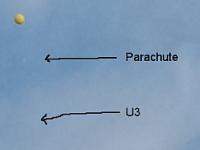
Click here to download the spreadsheet with the raw data and graphs. The photos below show the balloon during the early part of the ascent, payload construction, and graph of the telemetry collected during the flight. Click for full size versions of the photos.


The mystery
The last few moments of balloon flight S-5 are a bit of a mystery. Refer to the image showing the last WSPR transmission from S-5 and the last JT9 transmission. Notice that the signal strength at the start of the JT9 transmission is good, but quickly it gets weaker. In particular, the last JT9 transmission shows a rapid upward frequency drift, much more rapid than anything that we would normally see due to temperature change. Could it be due to landing in water? Will we ever know?