Gwyn G3ZIL wrote with some concern about the noise levels when using the Si5351A as Local Oscillator (LO) for a WSPR receiver. Subsequently he further investigated and concluded that the Si5351A can be modulated by mains hum, so very clean power supplies can be critical when using this device. The following article by Gwyn G3ZIP is reproduced with his kind permission.
Comparison of the performance of G3ZIL's Direct Conversion 7MHz WSPR receiver with a crystal LO and a QRP Labs Si5351A/Arduino shield LO
Setup
1. QRP Labs Si5351A/Arduino shield LO powered via 7805 regulator off an external "wall wart" which has a built in 7812 regulator, and for comparison, off a 15V manganese alkaline battery,
2. GG Direct Conversion 7MHz WSPR receiver main board (and LO when connected) powered from commercial bench PSU.
3. Signal source: Panasonic VP8193A synthesized signal generator with additional BNC attenuators where needed below 0.1 μV
4. Sig gen connected to input of a home-‐built diplexer, one output port connected to Rigol DSA815, with its pre-‐amp on and attenuation off, other output port connected to the antenna input of GG's DC receiver. Allows direct measurement of input signal when >0.1μV.
5. Where direct measurement not possible, input calculated from last measurement and in-‐line attenuators.
6. Total AF output of the DC receiver (peak at 1300Hz, -‐6dB at 300 and 2000Hz) measured by Racal Dana 9300B AC millivoltmeter.
Test Results
Figure 1. Total AF output over the band 300-‐2000Hz (‐6dB points) with RF input level (signal+noise) for GG Mk2 strip-board prototype at 10MHz (red), Mk2 PCB version at 7MHz (blue) both using GG's crystal local oscillator module compared with that when using a QRP labs Si5351A Synth LO with Arduino shield with the 7MHz PCB version, running on the good wall wart (green) and on a manganese alkaline battery pack (purple). The measurements suggest the noise over 3002,000Hz is equivalent to an input of ~0.08μV with the xtal LO and 1.5μV with the Synth when on battery, and 0.14μV when on battery.
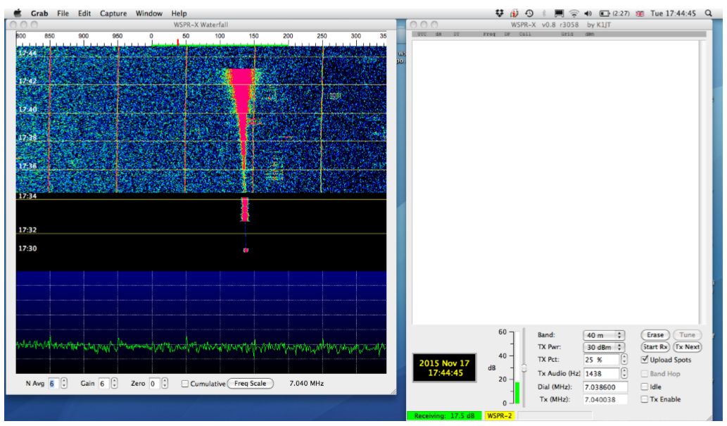
Figure 2. GG crystal LO WSPR waterfall display, settings N Avg 6, Gain 6, Zero 0, slider at 30dB. Note: "Receiving" level is 17.5dB (how measured unknown).
Signal levels as follows: up to 1736 ~5nV; to 1737 ~10nV; to 1738 ~20nV; to 1739 ~40nV; to 1740 ~82nV; to 1741 220nV; to 1742 400nV; to 1743 750nV.
Lower pane with spectrum generally just less than two divisions with odd harmonics of 50Hz up to 2.5 divisions.
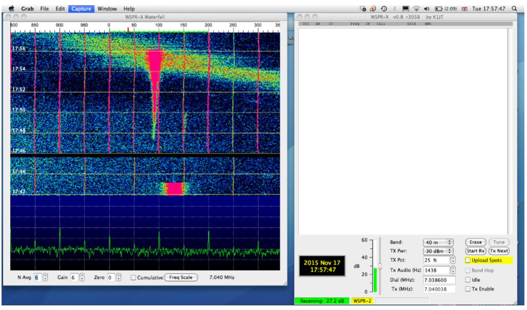
Figure 3. GG crystal LO WSPR waterfall display, settings N Avg 6, Gain 6, Zero 0, slider at 30dB. Note: "Receiving" level is 27.2dB (how measured unknown).
Signal levels as follows: up to 1749 ~5nV; to 1750 ~10nV; to 1751 ~20nV; to 1752 ~41nV; to 1753~82nV; to 1754 220nV; to 1755 400nV; to 1756 750nV.
Lower pane with spectrum generally just less than two divisions (perhaps v. slightly higher than GG xtal oscillator) with 50Hz harmonics at "900" and "200" Hz especially pronounced, up to 3.7 divisions
Receiver must be picking up an external broadband signal slowly drifting down in frequency from 1752.
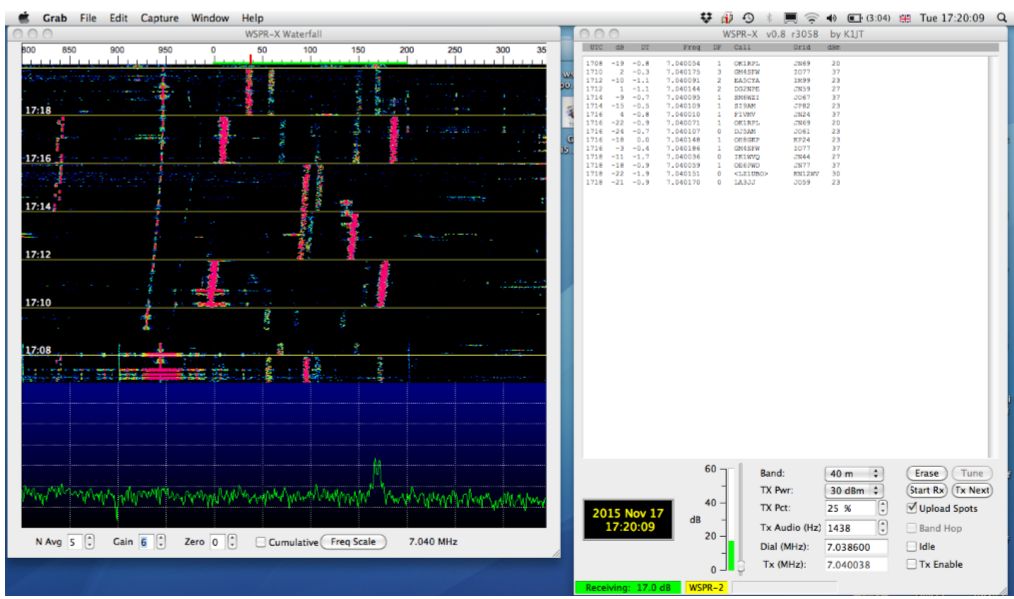
Figure 4. GG crystal LO WSPR waterfall display, settings N Avg 5, Gain 6, Zero 0, slider at ~3dB. Connected to an outside 40m dipole, in an urban area.
Note "Receiving" level is 17.0dB (how measured unknown). The bottom part of the upper pane, prior to 1708 is the end of the period with Si5351A Synth LO.
With the slider gain this low, for the xtal LO no lines from the 50Hz harmonics. "900" and "200" Hz lines visible in the period prior to 1708 on the Synth LO.
Note: drift is because the xtal LO was used directly from switch-‐on.
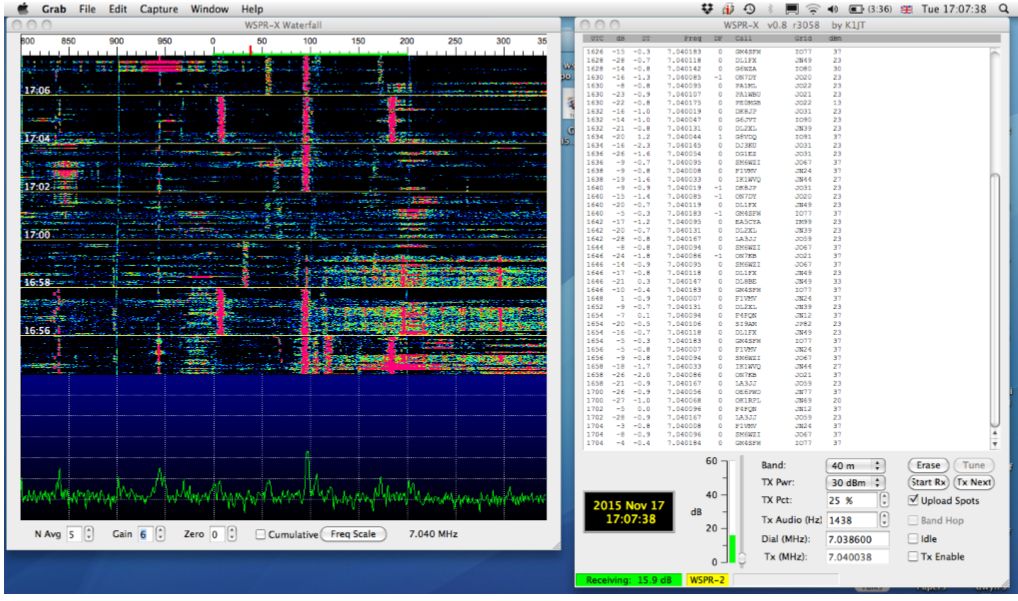
Figure 5. GG QRP Labs Si5351A Synth LO WSPR waterfall display, settings N Avg 5, Gain 6, Zero 0, slider at ~3dB (not touched between this and the xtal LO experiment). Connected to an outside 40m dipole, in an urban area. "900" Hz harmonic of 50Hz can be seen, that at "200" Hz less prominent.
Note: "Receiving" level is 15.9dB (how measured unknown).
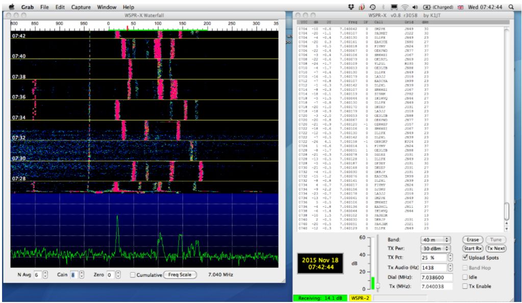
Figure 6. GG QRP Labs Si5351A Synth LO WSPR waterfall display, settings N Avg 6, Gain 6, Zero 0, slider at ~3dB. Connected to an outside 40m dipole, in an urban area.
The Arduino, the shield and the Si5351A synth are running from the same regulators as in the previous cases, but the input supply is a 15V battery. No trace of 50Hz harmonics can be seen.
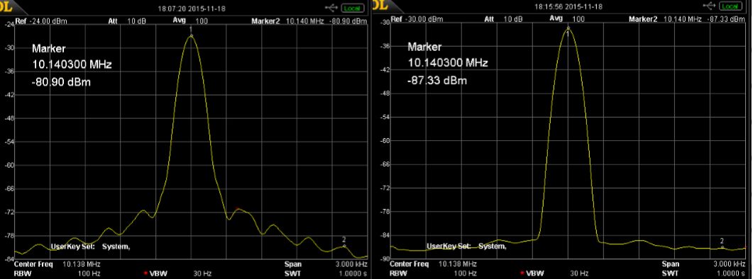
Figure 7. Spectra of the Si5351A CLK1 output with Marker 2 at 1300Hz above the centre frequency. This 1300Hz offset corresponds to "900" on the WSPR-‐X waterfall display, where a pronounced spectral line is seen. The actual output of the Si5351A is at about +10dBm, for these measurements the output has been passed through a narrow ~100Hz crystal notch filter. tuned to the exact Si5351A centre frequency. This reduces the centre frequency by ~35-‐43dB without affecting the sidebands greatly. This is necessary, as, otherwise, the DSA815 has too high a noise level to see the sidebands. Left: post crystal filter with the 7812 mains wall wart PSU. The 100Hz minimum resolution of the DSA815 is also a limitation. But these sidebands are stable -‐ the image is the average of 100 measurements. Right: Exactly the same conditions but with a 15V battery to power the Si5351A/Arduino Shield/Arduino. Note the minimum scale is now at -‐90dBm. The sideband at 600Hz is just noticable, but at 1300Hz it is at the noise level of the DSA. A deeper crystal notch would be needed to identify the sideband levels.
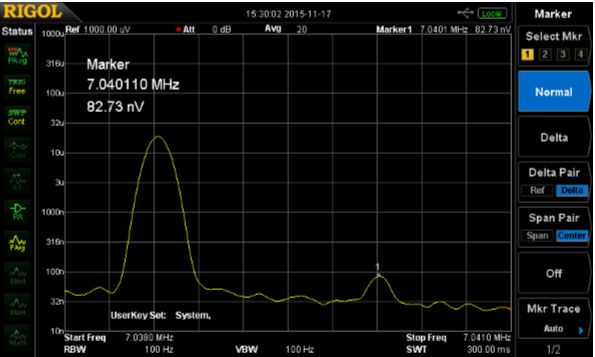
Figure 8. Example screen shot from the DSA815 connected to one output port of the diplexer, the other output port is connected to the receiver antenna socket. The diplexer input port is connected to the 8193A sig gen. The peak at 7.0386MHz is the residual (in this case Si5351A) LO signal after LO-‐RF port isolation in the DBM, the reverse attenuation of the RF amplifier and the diplexer output port-‐output port isolation. Marker 1 is the output of the 8193A sig gen at ~82nV.
Conclusions
1. The noise level of the broadband AF output from the receiver (300-‐ 2000Hz), when measured on an AC millivoltmeter, Figure 1, is a pessimistic indicator of the noise level relevant to decoding WSPR signals with the Si5351A as the LO. However, it is an appropriate measure if the intention is to use with SSB signals.
2. This is because, as shown on the spectrum display of the WSPR waterfall, the audio noise power is concentrated at discrete spectral line frequencies, at certain multiples of 50Hz, Figure 3. Apart from these discrete spectral lines the noise level is not noticeably different from that with a crystal LO with very careful power supply filtering. A 10nV WSPR signal would be above the receiver noise level. In almost all situations, when connected to an aerial, for WSPR use, the limiting factor will be the external noise and NOT the Si5351A sideband noise.
3. The higher noise level from the Si5351A synth is a direct result of using a mains power supply. Even a wall wart with a 7812 regulator and 1,000 microfarad decoupling, followed by a 7805 regulator and additional conventional decoupling within the receiver box is not adequate (Figure 7 left). The Si5351A is itself capable of much better performance, which can be seen in Figure 7 right, when powered by a battery. Knowing this, improvements to the decoupling of the mains PSU can be tried.
4. With a battery, the 300-‐2000Hz AF noise level with the Si5351A is about 6dB greater than the carefully decoupled crystal oscillator. This is of academic interest only, given the real-‐world noise once connected to an aerial.