|
|
10W HF Linear Power Amplifier. Comfortably produces 10W from 12V supply (CW, PEP and Digital modes). Compact design with huge heatsink included, which will not overheat even on continuous 100% duty-cycle operation. 26dB gain with +/- 1dB gain flatness from 1.8 to 30MHz. |

This 10W HF Linear Power Amplifier kit has no Surface Mount Components (SMD) to solder. There are a number of small transformers to be wound, and assembly requires care and patience.
The push-pull driver stage uses two BS170 transistors in the amplifier design used in the SoftRock transmitter stage. The final uses two IRF510 transistors in push-pull. Yes, this humble low-cost MOSFET really is capable of excellent performance all the way up to 10m band and beyond! Short lead-lengths and PCB layout are extremely important, they are the key to success.
Features:
- 10W output from 2 to 30MHz, using 12V Supply
- Suitable for 10W PEP, CW or Digital modes
- Generously-sized heatsink, will not overheat even on continuous 100% duty-cycle modes
- 2-stage amplifier provides 26dB of gain
- Push-pull driver and push-pull finals, for high linearity and low harmonic content
- +/- 1dB gain flatness from 1.8 to 30MHz
- 4dB down at 6m (50MHz) and 8dB down on 4m (70MHz)
- Standard 50-ohm output
- Through-hole plated PCB, several SMD components already pre-mounted
- PCB size 69.69mm x 33.97mm (2.744 x 1.338 inches)
- Standard inexpensive components throughout
- Tested for 1 hour at full-power 10W, 100% continuous duty-cycle with no forced air cooling
- Tested for 15 minutes at 20W, 100% continuous duty-cycle with no forced air cooling
- Tested at 20V supply
- Tested into open load, shorted load and various mismatches without instability (oscillation)
Assembly and operating instructions
The assembly document includes circuit diagram and detailed steps for the kit assembly. Please follow them carefully. Check your PCB Revision (written on the PCB silkscreen) and follow the correct assembly instructions for your PCB revision!
PCB Rev 3 Assembly instructions (PDF document revision 2.00, 13-Dec-2023)
PCB Rev 2 Assembly instructions (PDF document revision 1.04, 29-Nov-2018)
PCB Rev 2 Assembly instructions (PDF, Rev 1.03), RUSSIAN translation (thanks Andrey R1CF)
PCB Rev 2 Assembly instructions (PDF), FRENCH translation (thanks Gilles F1BFU)
This is an A4-size document, to print on letter size paper select "Fit to page" option in your print dialog box.
Photographs


Measurements by Allison KB1GMX
The following tests were undertaken by Allison KB1GMX on a production unit. They have been reproduced on three different kit assemblies. In all of the tests, there were no failures of components and no degradation of performance.
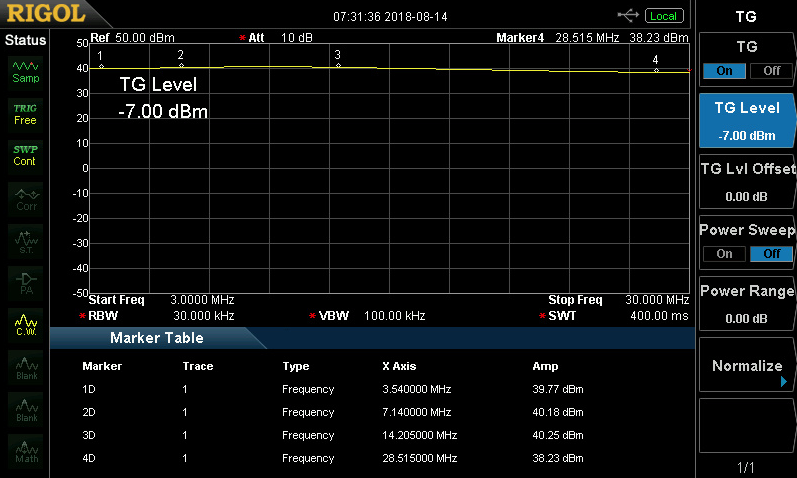
1) Gain: 26 to 28dB, with +/- 1dB gain flatness over the range 1.8-30MHz. This is shown in the following image.
2) Operation at full power into open output, shorted output, 20-foot long open cable, open cable with short – all with no oscillation or damage
3) Amplifier is still capable of 10W at 50MHz (6m band) though gain is down by 4dB compared to HF
4) Gain is 8dB down at 70MHz (4m band) compared to HF
5) With sufficient drive, the amplifier is capable of producing 20W output at 13.8V supply using +15dBm input, over the range 3-30MHz
6) Operated with +20V supply
7) At 10V supply still over 7W output
8) A clean 3.5MHz (80m band) source running at 10W output had 2nd harmonic at -38dBc and 3rd harmonic at -31dBc – very good linearity
9) Operated at full-power continuous key-down, 100% duty-cycle for 1 hour, without damage or degradation in performance.
IMD measurements by Geoff GI0GDP
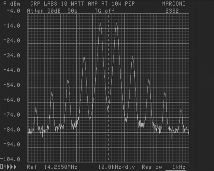
Geoff GI0GDP has measured the IMD performance of this Linear amp on 20m (14MHz) at full power 10W PEP output and found it to be very good. Geoff's test set-up:
- Supply voltage: 13.8V
- IRF510 bias: 150mA
- Signal source: two HP Signal Generators set to 14.250 and 14.260MHz, resulting in 13mW drive per tone which produces 2.5W output per tone, fed into a MiniCircuits combiner
- Marconi spectrum analyzer
The attenuation and reference level are set such that the two line (-4dBm shown) of the spectrum analyzer represents full power 10W PEP.
IMD3 is -30dB and IMD5 is -45dB relative to 10W PEP. Higher order intermodulation products are also seen to fall off steeply which is another important good characteristic.
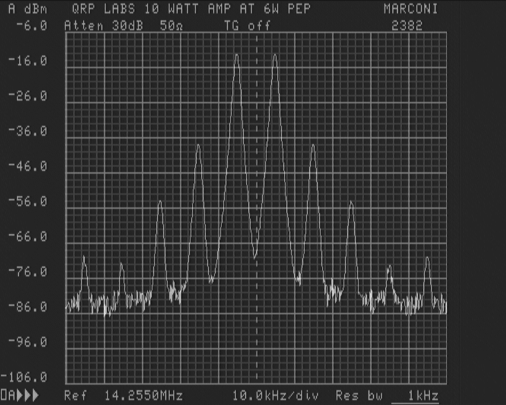
Geoff also reduced the drive from 13mW to 7mW, producing 6W PEP output; this image is shown below. Now IMD3 improves to -32dB and IMD5 improves to -48dB.
Geoff also tried the following:
1) Increase the IRF510 bias to 250mA per transistor: IMD3 stayed the same; IMD5 was 2dB lower, but IMD7 and IMD9 both dropped 6dB.
2) Tone spacing 2kHz instead of 10kHz: results unchanged
3) Inserting a 3dB attenuator at the input, cuts the output from 10W to 5W - as would be expected, another indication of good linearity.
Input impedance measurements by Fred WD9HNU
Fred WD9HNU made the following input impedance measurements with various VNAs (which agree)
Fred's measurements show input impedance peaking at over 400-ohms in a quite narrow around 60m and 40m bands; dropping nearer to 50-ohms at the extremes (160m, 10m). Practically speaking the impedance variations will not usually be a problem for a 50-ohm pre-driver stage output. The SWR will be high but this is not likely to be of any importance at such low powers. If worried about this, just put a 75-ohm resistor in parallel with the 10W HF Linear PA input. That will reduce the amp gain by a few dB but give a flatter SWR, if you care.


Fred also undertook a measurement of output power vs frequency at 12 volt supply. Fred writes:
"Power was measured using a signal generator, not terminated, connected directly to input at +10 dBm.
Power was then measured with a 3 dB attenuator in line which properly terminated the signal generator with the generator set to +13 dBm.
The output was the same in both cases."
| Frequency | Power (W) | Power (dBm) |
| 1.8 MHz | 2.7 W | 34.31 dBm |
| 3 MHz | 3.4 W | 35.31 dBm |
| 7 MHZ | 4.0 W | 36.02 dBm |
| 14 MHz | 4.4 W | 36.43 dBm |
| 21 MHz | 3.2 W | 35.05 dBm |
| 29 MHz | 2.1 W | 33.22 dBm |
Harmonic and phase noise measurements by Fred WD9HNU
"The signal generator is set for +10 dBm in, 12 volts supply, about 4 watts out. Terminated into a 40 dB attenuator before going to signal Hound SA44B spectrum analyzer. Attached files are just a look at the main carrier, the phase noise and lastly the harmonic content."
Note: Far right graph, this is the phase noise of the signal generator (Rigol DSG815). Next right, at the output of the Linear PA module, indicating no noticeable additional phase noise generated.
Note: On the harmonic content graph, 2nd from left, I have added combined two graphs from Fred. I have put the signal generator harmonic plot by itself (no amp) shown in RED. The output of the PA is shown in black. Note the low second harmonic at -38dBc as expected from the push-pull transistor configuration.
Low Pass Filters should always be used following any amplifier, even a linear. Filtering however, is less critical than it would be on non-linear amplifiers.


Video by Mark G0MGX
19-Jan-2022: I became aware of this useful video by Mark G0MGX, which includes voltage measurements at various parts of the circuit, and is very useful for debugging problems: https://youtu.be/XgqjexAFDYg