Specifications
Onboard battery
Connecting to Ultimate-series kits
Photos
2-diode supply voltage regulator
Review
1pps signal characteristics
1pps accuracy measurement by David G0LRD
David G0LRD on GPS Sensitivity
Eddie G3ZJO experiments with the GPS antenna location
NOTE: QRP Labs is now supplying a newer GPS module, the QLG1 kit.
The Skylab SKM52 is a high performance GPS module suitable for the Ultimate1, Ultimate2 and Ultimate3 QRSS/WSPR kits. Compared to the previously supplied VK16E module, the SKM52 GPS receiver module has higher sensitivity and a much more accurate 1pps signal (10ns RMS accuracy, compared to 1us on the Sirf III-based VK16E module). On the other hand, the SKM52 module requires a 3.3V supply (not the 5V used by the Ultimate-series kits), so you will need an additional regulator. I am preparing a voltage regulator kit too, but it is not ready yet.
When used with the Ultimate QRSS/WSPR kits, the GPS module will provide accurate time-keeping, frequency calibration, and location information (for encoding the Maidenhead locator automatically into WSPR messages).
CLICK HERE to read the SKM52 datasheet.
Main features, from the datasheet, are:
- Ultra high sensitivity: -165dBm
- Timing accuracy (PPS) 10nS RMS
- Extremely fast TTFF at low signal level
- Built in high gain LNA
- Low power consumption: Typical 20mA @ 3.3V
- NMEA-0183 compliant protocol or custom protocol
- Operating voltage: 3.0V to 4.2V
- Operating temperature range: -40 to 85℃
- Small form factor: 20x20x4.9mm
- RoHS compliant (Lead-free)
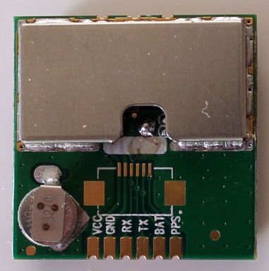
Notes on the onboard battery
There's a small battery on the GPS module board as you can see in the photo. The use of this battery isn't at all clear, from the datasheet. Even the existence of it isn't mentioned in the datasheet. The datasheet talks about the battery connection, for supplying backup power externally, but not the onboard battery. Some purchasers have queried the fact that the module is supplied wrapped in aluminium foil and the battery is flat. Well, the modules arrive from the supplier in large ESD-proof (Electrostatic Discharge) plastic trays carrying 24 modules per tray, and the battery voltage measures zero. When they are shipped out individually, they are wrapped in foil to protect against ESD. This makes no difference, because the battery voltage was already zero. Furthermore, the use of the battery isn't clear. So please, just ignore the battery, connect 3.3V to the module and everything will work fine.
Email from David G0LRD
David made a discovery which seems to resolve the battery mystery. It appears to be a rechargeable cell which allows the SKM52 to retain information on its last satellite fix, permitting a faster startup. David writes:
"I have had a play with the GPS module. I've managed to keep it neat by fitting 0603 pull-up resistors on the small empty area behind the contact pads. The discovery I've made is about the mystery battery. This is, as far as I can tell, a rechargeable lithium cell that it hooked up to the GPS chipset standby supply input via a charging resistor/diode. Although it has zero volts when supplied, when power is applied to the board, the cell quickly comes up to 3V, and when power is removed the cell remains at 3V as does the 'BATT' contact pad. "
Notes on Connecting the SKM52 to Ultimate-series kits
1) You need to connect 4 wires to the GPS: Vcc, Gnd, TX and PPS. The Gnd, TX and PPS wires can be connected straight to the Ultimate kit (it is suitable for use with Ultimate1, Ultimate2 and Ultimate3 kits). Note that the GPS "TX" output is connected to the Ultimate kit "RxD" input.
2) The SKM52 module requires a supply in the range 3.0 to 4.2V, which is below the 5V supplied by the Ultimate kit connector pin. You must use either a 3.3V regulator, or two diodes in series to drop the voltage (see below).
3) The datasheet recommends that a 10K pull-up resistor should be connected from the Ultimate kit's "RxD" input to the +3.3V supply of the GPS module. Constructors have reported: the pullup resistors are NECESSARY!
4) The SKM52 GPS module has a high sensitivity, but you may still want to look out for issues if you use it indoors and your building has a steel frame (Faraday cage behaviour) etc. GPS modules may also be disrupted by RF from the Ultimate kits. I suggest that it is worth connecting a few metres of screened cable between the Ultimate kit and the GPS Module, with the screen connected to Gnd at the Ultimate kit end of the cable.
5) The default 9,600 baud rate settings of the Ultimate kits will work fine with the SKM52 GPS module. On the Ultimate3 kit use GPS Mode 1 or 2.
6) On the later firmware versions providing Huff Puff frequency calibration, you should not need this HP method with this SKM52 GPS Module because the timing accuracy on the 1pps pulse is specified as 10ns which is already very accurate. So you can leave Cal HP = 00 and Cal Time = 010 (the default parameters, which specify the non-Huff Puff behaviour). Or, use the HP method, it will work fine too.
7) I recommend use of recent firmware versions, preferably the latest versions. Firmware upgrade chips are available for each Ultimate kit, from QRP Labs. If not using the latest firmware version, then please check the appropriate page for your kit, and see if your firmware version has been superceded by any useful changes in relation to GPS.
Photos
Please click on the thumbnail images to see larger versions!


Two diodes voltage regulation
|
|
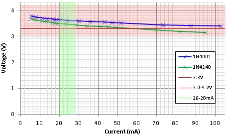
Two diodes can be connected in series as a voltage regulator, to drop the voltage from 5V supplied by the U3, to the lower voltage required by the SKM52 GPS module (nominally 3.3V).
The voltage regulation is imperfect, but adequate for powering the SKM52 GPS module, and this is a very simple and inexpensive solution. Any common diodes should suffice. I took measurements at different current consumption, and charted them (see right) for common diode types 1N4001 and 1N4148. The shaded pink area shows the allowable supply voltage range of the SKM52 (3.0-4.2V). The shaded green area shows the specified current consumption range (20-28mA). It can be seen that the two diodes produce good enough voltage regulation to keep the voltage well within the required range. Several constructors have emailed to confirm the approach works perfectly. |
Review
Thanks to this most well-known and well-respected afficionado and connoiseur of GPS modules, Eddie G3ZJO for his testing of a sample SKM52 with the Ultimate3, and providing the following review:
The module has a small back up cell on board.
I used all the decoupling and pull up resistor(s) as recommended in the Data Sheet and a 3v3 low dropout linear regulator. The module is a SMD but soldering wires to the provided tabs was no problem. I used 5 wires (I have a supply on the Bat back up connection) all the same colour (green) as this was the only wire to hand which was soft enough, to connect the module to my standard, PSU / interface board design. A good source of fine flexible insulated wire is from thin multicore screened cable although in some the insulation can be quite stiff.
Cold Start:
I set GPS Mode = 1, Cal HP = 00, Cal Time = 010. Initial acquisition took a few minutes and 3D lock followed.
Accuracy:
No variation was seen in the accuracy of each Cal. session. My now standard set up, Cal HP = 02, Cal Time = 240 gives an advantage to combat DDS oscillator thermal drift, from observation of the 125MHz signal.
Sensitivity:
To check sensitivity I removed the module from the shack window for 20 minutes and 3D Lock continued.
Conclusion:
As far as I can tell the SKM52 Module would appear to perform to the published Spec. and within the test parameters tried, as good as the Trimble Sylvania and Reyax UP501.
1pps signal characteristics
The following are 'scope images of the 1pps signal, sent in by Ulli DC8SE.


1pps accuracy measurement by David G0LRD
David G0LRD has measured the accuracy of the 1pps signal in comparison to his Rapco 1804M Frequency Reference. David writes:
"I tested the GPS 1PPS performance against my Rapco 1804M Frequency Reference, which is a professional-grade GPSDO. (This is so stable that the control system only updates the frequency-steering DAC once or twice a day on average.) The first scope capture shows the performance with a good signal (10-11 satellites used). The second shows the performance with a marginal signal (just enough for it to turn the 1PPS on). The Blue trace is the reference pulse. The yellow is the SKM52. I've turned on infinite persistence so that all the pulses are visible.


"Findings:
"1- With good signals (1st image) the SKM52 seems to lead the reference pulse by ~290ns. Of course, this doesn't matter for frequency calibration. The cables were not the same length, but not so much to explain this difference.
"2- The total jitter is 20ns peak to peak. Not quite 10ns RMS, but close enough for me!
"3- With marginal signals (2nd image) the jitter is much worse ~400ns p-p (note timebase is doubled to 100ns/div)"
Upon further discussion about the RMS timing accuracy, during which I commented that the first scope trace says 2.9ns standard deviation:
"Thinking about it again, the jitter was 20ns 'pk-pk', so I think the RMS equivalent is (pk-pk / (2* squareroot(2))) = 7ns, so well within spec. (I'm not sure that Standard Deviation is quite the same thing as RMS, but stats is not my strong point.) Something I noticed when making the measurement was that the offset changed in a 'sawtooth' manner ( a plot of the offset would have looked much like a sawtooth). I've read somewhere before that this 'sawtooth' is typical behaviour for a GPS 1PPS.
"The SKM52 is definitely an excellent performer. The 1990's era GPS unit in my reference can only track 6 satellites and needs a huge signal to work. This is the first GPS I've used that works reasonably well indoors in my shack."
David G0LRD on GPS Sensitivity
David found the SKM52 GPS was desensitised when connected to the U3. He made a number of modifications, and the problem was resolved. Unfortunately they were all done at once so it is not clear which one (or ones) actually resolved the issue. So if you face an issue where the SKM52 seems insufficiently sensitive, you may want to try one or more of the following.
1) Added a dedicated 5V low-drop voltage regulator instead of running the SKM52 GPS direct from the lab PSU
2) Replaced a 2-diode voltage dropper with a dedicated 3.3V LDO voltage regulator
3) Added 20K in series with the Serial GPS Data (as well as the recommended pull-up at the GPS end). David says this really cleans this signal up (but it is still plenty "square" enough), and stops the associated noise on the other pins.
4) Added some bulk decoupling across the U3 supply (100uF)
In a subsequent email David also notes: "I noticed another characteristic of the SKM52. I found that the sensitivity is much improved simply by ensuring the U3 itself is not in the main lobe of the antenna, i.e. the U3 should sit below the plane of the GPS pcb by tilting it slightly. Provided this is done, the GPS module can be situated quite close to the U3."
Eddie G3ZJO experiments with the GPS antenna location
Eddie investigated the variation in GPS module performance with the module placed in different locations relative to the U3, to investigate how proximity to the U3 affected the module. This experiment was done with the SKM52 module but the results should also apply to the newer SKM61 GPS module. His conclusion is interfering noise from the U3 is conducted to the GPS antenna, so that the proximity to the module is less important than having it electrically separated by 2 metres of screened cable. Read Eddie's PDF document (179KBytes) here.