|
|
A programmable crystal replacement. It has three independent outputs with frequency range 3.5kHz to approx 300MHz, and can be optionally GPS disciplined. Configuration is by a micro-USB connector and PC terminal emulator |

The features of this module are as follows:
- Tiny size PCB, a little smaller than an HC6 crystal: 0.725 x 0.675 inches (18.4 x 17.1mm)
- Factory assembled, ready-to-use (no assembly required)
- 3 independent 3.3V p-p squarewave outputs (2 if you use GPS discipline)
- You can feed the outputs through LPF kits to get sinewave outputs
- 8 selectable “banks” of frequencies, chosen by 3 input control signals
- Frequency range 3.5kHz to 200MHz from onboard Si5351A or MS5351M
- Extended frequency range up to approx. 228MHz if you don’t mind violating the Si5351A datasheet specifications
- Quadrature output mode (Clk0 and Clk1 on same frequency but configurable 0, 90, 180 or 270-degree phase offset)
- GPS frequency discipline using 1pps from a GPS receiver
- Power supply voltage 3.5 to 12V DC
- Frequencies and configuration stored in non-volatile memory for next power-up
- QRP Labs Firmware Update (QFU) bootloader
This module is the replacement for the original ProgRock kit. It is much smaller than the original ProgRock and ready-assembled. It does not have ProgRock's 4-way DIP switch for programming (which was a bit awkward anyway); there is a USB-C connector for programming via a PC serial terminal and for firmware updates. (Note, PCB Rev 1 and Rev 2 have a Micro-USB connector. PCB Rev 3 currently being supplied, is USB-C).
Documents and resources
Manual - version 1.00b (released 17-Feb-2023)
Firmware version history
Please refer to the manual for the firmware update procedure, which is very easy and does not require any special hardware, software, drivers etc. It requires only a PC and a USB cable. Click the file in the first column of the table below, to download the firmware file of interest. Note that firmware files are encrypted and can only be used on the QRP Labs ProgRock2 board.
Firmware version history:
| Version | Date | Contents |
| 1_00 | 15-Feb-2023 | First firmware version |
| 1_01 | 13-Mar-2023 | - Bug fix: spurs only -45dBc existed, now gone |
Photographs


Several ways to install the ProgRock2 module in your projects:
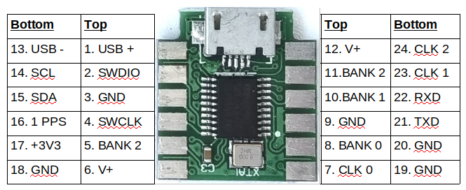
1) You can choose the pin headers option at checkout. The board fits in between the rows of headers. So it can be plugged in to a 2x6 pin female socket on a motherboard. The board was carefully designed such that the three BAND select, 3 clock outputs, and power rails are all accessible along one edge.
2) Another option at checkout is the right-angled 2x6-pin headers; these can be installed also by sliding the PCB edge between the pins as shown; then the full 24 connections are available. That could be soldered into a position on your board, or plug into female pin header connectors, for example.


Yet another way is to install the ProgRock2 module inside its very own enclosure, an HC6 crystal case! The ProgRock2 module was specially designed such that the pads at the board end are Gnd, V+ and CLK 0. One of the HC6 crystal holder pins can be soldered to V+, the other to CLK 0, and the ground connection made to the enclosure.


Finally, what about old-school PCB edge-connectors... this picture shows the little test and bootloader flashing jig in use at QRP Labs HQ for preparing all ProgRock2 boards. The 0.1-inch pads line up nicely with the edge connector sprung contacts. This particular one is many decades old.


Nice web page about ProgRock2 by Breck K4CHE
Click here: http://k4che.com/Progrock2/progrock2.htm