Notes on the use of a GPS module with the QRSS "Ultimate" kit:
1) In order to enable the GPS module functionality you need the "Use GPS" parameter on the kits configuration menu set to "ON".
2) A 1 pulse-per-second (pps) input signal to the kit is a REQUIREMENT when in the GPS module is enabled. Without a valid 1pps input, the kit won't function. The 1pps signal is sufficient to operate the kit, lock the frequency and provide accurate time-keeping, with or without the NMEA serial data input from the GPS
3) The optional NMEA serial data input is used to extract the time, longitude and latitude from the $GPRMC sentence
Suitable GPS modules
Not all GPS modules are suitable for use with the kit. It is important to check the features of your GPS module before buying! The main requirements on the GPS module are:
a) It must provide a 1pps output
b) If you wish to use the serial data for location and time information, the module must supply a serial data output in NMEA-0183 format, and the output must contain the $GPRMC sentence. This sentence is the most common GPS sentence anyway so is usually included as long as the GPS supports the NMEA-0183 output.
c) The QRSS kit does not communicate with the GPS module, it only listens to the GPS module's 1pps and serial data outputs. So it is important to understand what mode your GPS module starts in by default. Even if the module has an NMEA-0183 output, if this is not the default output mode it will still not work, unless you have a way to set the module to NMEA-0183. Sometimes you may be able to connect the GPS to a PC, set the default output mode, and the GPS may remember that setting at next switch-on. It depends on the individual GPS model.
d) Another point to bear in mind is the GPS antenna. Some modules have a built-in antenna. Others require you to add one.
Tried-and-tested GPS modules
The following modules are known to work with the kit. The table gives a source if known, and the appropriate "GPS Baud" setting to use in the kit, to suit the GPS module's default output configuration with the kit:
| Model | Antenna | Source | "GPS Baud" | Comments |
| EM-406A | Built-in | Sparkfun or Expansys or Proto-pic | 04800,01,1,8 | Use 10K pull-up resistors from 1pps and Serial signal to +5V |
| uBlox TIM | External | 09600,01,1,8 | See GPS Ref | |
| Trimble ACE iii | 04800,01,1,8 | must be configured for $GPRMC using software called NMEATool, through a MAX233 level converter so that serial port can communicate with the GPS module. | ||
| Trimble Silvana ACM | Built-in | dpieshop | 09600,0,1,8 | Uses Trimble Condor C1919A GPS module; requires 3.3V regulated supply |
| GP-GS010 | 09600,01,1,8 | See datasheet |
The GPS stabilisation strategy
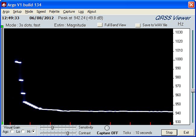
Here are some notes about how the GPS stabilisation takes place in the kit. There are a number of challenges here. On the one hand, you want the frequency control to be fast enough that it can attack a tuning inaccuracy or temperature drift quickly. On the other hand, it needs to be slow enough that it doesn't cause too much frequency ripple. The result is inevitably a compromise.
The first thing about the frequency locking method is to realise that the microcontroller measures its own system clock, which is also the RF output frequency since the same crystal oscillator is shared by the processor and the output amplifier. The frequency is measured by just counting the number of system clock pulses between the arrival of two successive 1-pulse-per-second signals from the GPS module.
In order to obtain an accurate count of the baseline (unshifted) frequency, the output frequency needs to be constant for more than 1 second, and the Frequency Shift Keying (FSK) during that second has to be set to zero. Clearly in some output modes, such as WSPR, it is not possible to run the frequency lock during the RF transmission because the frequency changes too quickly.
In the QRSS, FSKCW and DFCW modes, frequency stabilisation only occurs when the RF output is ON, and the FSK is zero. In the QRSS mode this means during key-down only. In the FSKCW mode, it means during "key-up", i.e. the low part of the waveform (the RF output is always on in FSKCW mode). In DFCW, frequency correction occurs during the morse "dits" which are at FSK = 0.
In the case of the CW, Hell, Slow-Hell, DX-Hell and WSPR modes, frequency stabilisation only takes place while waiting, i.e. in between transmissions. You can therefore only use the GPS-discplining (stabilisation) feature of the kit in these modes if you have the FRAME configuration parameter set to a non-zero value. In WSPR mode you are ALWAYS using the FRAME parameter.
In the TEST mode, there is no frequency stabilisation at all. When the GPS 1pps signal is present and GPS is enabled, the TEST mode provides a straightforward frequency counter function, which displays the measured frequency on the LCD display. This can be used to adjust the trimmer capacitor to get the frequency near the desired frequency.
The actual frequency correction is achieved by first measuring the frequency as the number of system clock cycles between successive 1-pulse-per-second signals from the GPS. The required correction frequency is calculated as the difference between the "Frequency" configuration setting and the measured frequency.
TO BE CONTINUED...

