Dev Update 28-Sep-2020
This article is about solving the problem with microphonics.
Microphonics in the QCX-mini
It became apparent during testing that the QCX-mini prototype was highly microphonic. Pressing the rotary encoder shaft was the most noisy operation. But pressing the other buttons also generated pops and even turning the rotary encoder during tuning, generated audible clicks. After initially investigating electrical reasons such as grounding and PCB layout, I determined that none of that was a problem; the problem is the microphonic nature of the QSD capacitors C43-C46 (and to a lesser extent, others); it was easy to prove just by tapping the board with a ceramic screwdriver; the exact capacitors could be found by tapping various capacitors with the screwdriver until the loudest pop was found, C43-C46 being very readily apparent.
The problem arises because high-K dielectrics used in high density capacitors, type MLCC (Multi-Layer-Ceramic-Capacitors). MLCC capacitors can provide high capacitance in a small volume and at very low cost. However, the high-K dielectric is a piezo-electric material. Vibrations generate a small voltage, in effect, the capacitor behaves as a microphone. This is a very good paper on the topic:
https://sh.kemet.com/Lists/TechnicalArticles/Attachments/62/2007%20CARTS%20-%20Reduced%20Microphonics%20and%20Sound%20Emissions.pdf
There are many other interesting references around the internet.
C43-C46 are sited close to the PCB mounting pillar of the Controls PCB. They are also in the most sensitive part of the circuit, where any piezo-electrically generated voltage is added to the signal path when the signal is at its smallest level, and is subsequently amplified by up to around 100dB.
The QCX and QCX+ radios have no problems with microphonic components. This is despite the use of high capacitance MLCC. An investigation shows that the MLCC used are actually none other then standard 0603-sized SMD MLCC capacitors, with wires soldered on, and dipped in a blob of yellow stuff then the value printed on the outside. The photographs below show the 0.47uF capacitor used in the QCX+ kit as the QSD sampling capacitors C43-C46 for example.


So why does this 0603-sized capacitor cause a problem in the QCX-mini, but not in the QCX+? The reason is that in the QCX+ it is suspended above the board on wires, as a through-hole component. In the QCX-mini, the capacitor (0603 MLCC) is soldered rigidly onto the PCB itself, being SMD, and all the vibrations present in the PCB are applied to the capacitor effectively. It also appears to me, during my experiments with scratching the surface of capacitors with my ceramic screwdriver that the encapsulated 0603 SMD capacitor that is presented as a through-hole capacitor is much less sensitive than a bare SMD capacitor. The yellow stuff must be acting to damp vibrations reaching the tiny 0603 SMD capacitor inside.
Possible solutions
I asked the QRP Labs discussion group for advice on this issue and there was a very interesting discussion, see this topic:
https://groups.io/g/QRPLabs/topic/advice_wanted_qcx_mini/77059114
Possible solutions can be categorized as:
- Damping the vibrations
- Use of different types of capacitor e.g. NP0, film, tantalum
- Use of through-hole capacitors to replace the sensitive SMD ones
Damping the mechanical vibrations could at the most primitive end, sticking a blob of blu-tac (putty) over the offending capacitors; more advanced solutions could include rubber fittings between the controls PCB and the main PCB, conformal coatings to the main PCB, rubber O-ring, moving mechanical pillars, etc. A sub-category could be designated for some suggestions to re-orientate the capacitors in a different plane e.g. on their end tombstone style, or sitting up on their side. All of these ideas suffer from two major problems:
a) They would be expensive to implement (rubber fittings, conformal coatings), or non-manufacturable (SMD components in non-standard orientations);
b) Damping may provide some dB of improvement but it was my intuition damping would not come close to removing the quite serious pops; much more than a few dB is required.
NP0 capacitors have a Class-I dielectric which is low-K and has very low piezo-electric effect. However they also have lower density. A 0.47uF capacitor as an NP0 is available from Digikey but the size is SMD 2022 and the cost is $1.83 per capacitor even in volumes of 1000. This capacitor is therefore large and prohibitively expensive. Various types of film capacitor could solve the problem, they are still very expensive compared to MLCC and also larger; one correspondent raised concerns about reliability (un-encapsulated film capacitors can crack as they age).
Replacing the sensitive SMD capacitors with through-hole variants seems a good option, provided enough physical space can be found to accommodate them. The through-hole capacitors contain the same SMD MLCC Class-II dielectric high-K capacitor inside but experience with the QCX and QCX+ shows that they do not generate microphonics when encapsulated in the yellow blob, and when they are not bonded rigidly to the PCB but suspended on wires instead.
Google about this problem! It is very interesting - the electronics industry and particularly audio electronics, have gone to a lot of effort to solve this problem with various types of exotic SMD capacitors, including film capacitors and SMD MLCC on more flexible mounting structures which don't transfer the vibration so effectively. We do have the luxury here that this QCX-mini is a kit, to be assembled by the constructor, we do not HAVE to use SMD for everything!
So the only questions are then, which SMD capacitors need to be replaced with through-hole and how can the board assembly be modified to make sufficient space for them?
Replacing the QSD capacitors C43-46
I tried some of the lab techs' play-doh (blu-tac not being anywhere to be found) and did not notice any improvement from this form of damping.
I removed the four 0.47uF capacitors C43-46 and soldered on through-hole capacitors. Immediately there was a substantial reduction in the amount of pop, but the pops were still readily audible. I next replaced the 0.47uF capacitor C11 and the 0.1uF capacitor C12 in the phase shift section of the circuit (IC6/7) and noted further improvement.
But this "improvement" and "further improvement" all seemed rather unscientific, I decided I needed a more quantitative way to measure improvement.
The more scientific approach
My first idea was to feed the audio into my PC and use the Argo spectrum analysis program, with which I am familiar, to measure the pops. This method did work, by pressing the rotary encoder shaft, then stopping Argo, and hovering the mouse cursor over the "pop" then reading off the dB level. But it still felt rather imprecise as it depends exactly where the cursor is placed etc.
What I really wanted was a way to chart the signal amplitude vs time, in the CW filter bandwidth.
The QCX itself comes to the rescue! It has a built-in single-bucket DSP (Goertzel algorithm) which is a 250Hz filter bucket centered on 750Hz. This is used to provide a numeric amplitude of the filtered audio to the CW decoder algorithm, and is also used in the QCX's built-in alignment tools, when peaking the BPF and aligning the unwanted sideband cancellation circuits. The QCX has a CAT serial port too, and so it was a very trivial modification to temporarily add a few lines of code to dump the Goertzel algorithm result to the CAT port once every 4 milliseconds (250 times per second). Then I can copy and paste from a terminal emulator to a spreadsheet and do averages, logarithms, charts, whatever I like!
I use an Arduino as USB to Serial converter running a very simple sketch see below.
#include <SoftwareSerial.h>

SoftwareSerial mySerial(10, 8); // RX, TX

void setup() {
  // Open serial communications and wait for port to open:
  Serial.begin(38400);
  while (!Serial) {
    ; // wait for serial port to connect. Needed for native USB port only
  }
  Serial.println("Monitoring serial!");

  // set the data rate for the SoftwareSerial port
  mySerial.begin(38400);
}

void loop() { // run over and over
  char c;

  if (mySerial.available()) {
    c = mySerial.read();
    Serial.write(c);
  }
  if (Serial.available()) {
    mySerial.write(Serial.read());
  }
}
The Arduino IDE has a built-in Serial Monitor so this is a very easy way for me to get serial data out of a project and I do this often when I need to log some data from my projects. Actually it's usually the ONLY thing i use my original first edition Arduino Uno for!
Below are photographs of my experimental setup. The QCX-mini is suspended on four 25mm nylon spacers. I installed a specially assembled Controls PCB which contains just one button and the rotary encoder, whose connections are not soldered to anything. I merely want to use it to generate the mechanical shock that will be transferred to the main PCB and cause the microphony. A short cable (cut from an old pair of earphones) connects the 3.5mm stereo CAT port output jack to the Arduino, which is connected by a USB cable to the PC. The Altoids tin contains a QRP Labs Dummy Load.


NOTE that the gain potentiometer is not installed, it is replaced by two 3.3K resistors, these set a fixed mid-range gain so that I know all measurements are done at the same audio gain level. I don't really care what the level is because I will be looking for relative improvements; I just want to make sure that the audio gain level is at a constant setting throughout the experiments.
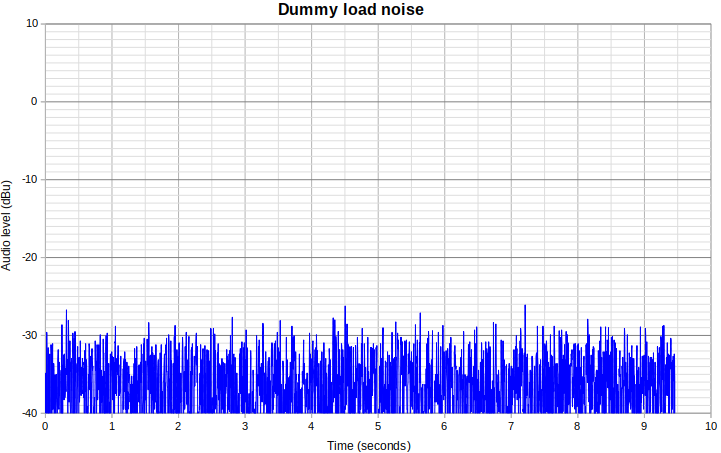
Dummy load noise
First it's important to have a reference noise level. This plot shows approx 9.5 seconds of recording the noise with the QCX-mini connected to a dummy load. The average noise floor level is at -37.6dBu.
Antenna noise
Next I wanted to know the level of noise when the QCX-mini is connected to the antenna. This was done in a quiet part of the 20m band during the daytime (early afternoon). I switched off the computer and everything else in the lab because I know that my computer increases the noise floor on 20m band. Since my computer was switched off I couldn't use the Arduino method to record the levels :-) So I used QCX menu 9.3 which displays an average of 64 measurements on audio channel 1 (from the output of the QCX audio amp, IC10b), updating approximately 4x per second. I video'd 10 seconds of the action on my phone, then replayed it at 4x slower speed and typed the measurements in to the spreadsheet.
I was able to average the measurements and convert them back to the dBu scale used above. The average antenna noise sat at -20dBu.
In all further measurements below, I have scaled the vertical axis as dB relative to the 20m band noise, set at 0dB.
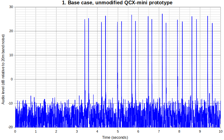
Experiment 1: Base case, unmodified QCX-mini prototype
For the first experiment I put back all the SMD capacitors I had replaced (see above) so that I could start again from the beginning, in an orderly and (somewhat) more scientific way. So this first graph is obtained with effectively an unmodified QCX-mini prototype.
The rotary encoder shaft button was pressed as gently as possible, 10 times (only 9 of these are shown in the graph below, to keep everything on a standard equal 10 second measurement interval).
In the chart you can see one pop when the button is pressed, and another when it is released. Nasty stuff! The worst peak is 45dB over the dummy load noise floor! Which is around 27dB over the band noise.
This is a zoomed in chart, to examine one of those button presses; actually the 5th one; I have zoomed in to show the interval 6.4 to 6.7 seconds:
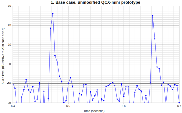
It can be seen that the impulse shock of the button press is very short. The nature of the recording method is to provide the amplitude of the sound in a 250Hz bucket centered on 750Hz, so the updates are provided once every 4 milliseconds. It would have been nice to have finer resolution, since the true peak intensity will always fall between two buckets on either side, which will be lower than the peak. Because of this, I felt justified in my measurements in taking the WORST case spike of the 10 button presses (20 pops, considering one pop occurs on pressing the button and another on releasing it).
It should also be noted that even taking the worst of 10 presses doesn't exactly reproduce the precise same measurement every time; for example I performed the base case measurement three times and obtained three figures +44.8dB, +46.2dB and +45.1dB (dB relative to the dummy load noise floor). In cases where i measured more than once, I am taking the average.
Yes I know this is all a bit approximate but that's fine, I am not trying to start a whole multi-week research project here, just somewhat methodically identify the effectiveness of remedies.
It will also be interesting to state each measurement relative to the band noise (-20dBu). Accordingly we can say that in the base case, the amplitude of the pops is +28dB relative to the 20m band noise (average of three measurement runs).
To summarise:
- Record the 250 samples per second for 10 seconds, during which I press the rotary shaft encoder button gently, 10 times
- Take the worst of the 20 pops, measured in dBu, and calculate the dB relative to the 20m band noise measurement
- In cases where more than one measurement run was performed, average them
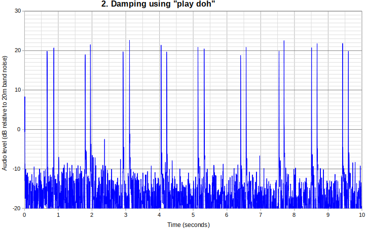
Experiment 2: Damping with "putty"
I wish I knew where my blu-tac is, but I don't. Nevertheless the most senior of the junior lab techs most certainly did know where her play-doh was, and so I used that as a convenient substitute. (CLICK PHOTO BELOW for a larger version).

I was actually quite pleasantly surprised that despite my negative expectations, there was actually a measurable improvement!
The measurement is +23dB, which is 4dB better than the base case.
Experiment 3: Pressure point damping
In this experiment I applied very firm pressure with a screwdriver right next to the base of the plastic pillar that attaches the Controls PCB, and also at various other points around the main PCB.
The most improvement I got compared to the base case (unmodified QCX-mini) was about 2dB improvement. Unspectacular...

Experiment 4: Damping using silicone pads
In this experiment I took two silicon pads, of the type used to electrically insulate the IRF510 MOSFETs from the heatsink in the QRP Labs 10W Linear and 50W QCX PA kits. After the surprising success with the play-doh I really thought I might see this silicone pad having some beneficial effect on the situation, damping the vibration reaching the main board. But: no joy, there was absolutely no benefit as far as I could measure.

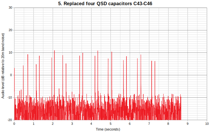
Experiment 5: Replacing C43, C44, C45 and C46 (the QSD capacitors)
Capacitors C43-C46 were replaced with through-hole capacitors from the QCX+ kit (one QCX+ kit having already been raided, to provide enough parts to build the second QCX-mini prototype).
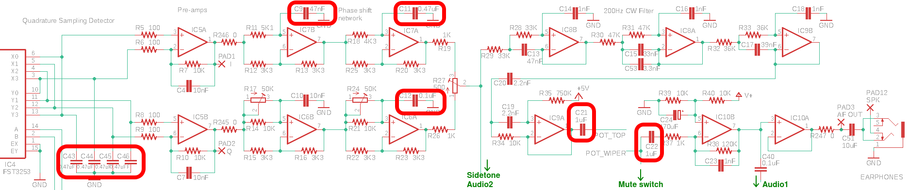
Refer to the circuit diagram section below, which shows the audio stages of the QCX-mini, starting at the left with the quadrature sampling detector, with the signal flowing through to the earphone output at the right. The capacitors which are replaced in experiments 5 to 10 below, are circled in red (Click the image for a larger version).
This provided the most spectacular improvement to date. The measurement is +10dB relative to the 20m band noise.
But the pop is still noticeable. So the hunt has to continue. "The hunt" proceeded by turning the PCB over to expose the underside where most of the resistors and capacitors are, and scratching each capacitor with my ceramic screwdriver blade while listening to how much noise that made in the headphones, to try to identify the next most important capacitor.
Experiment 6: also replace C11 (0.47uF in phase shift circuit)
C11 was identified as the next most important capacitor and replaced with a through-hole capacitor.
There was slight improvement, the measurement is now +9dB relative to the 20m band noise.
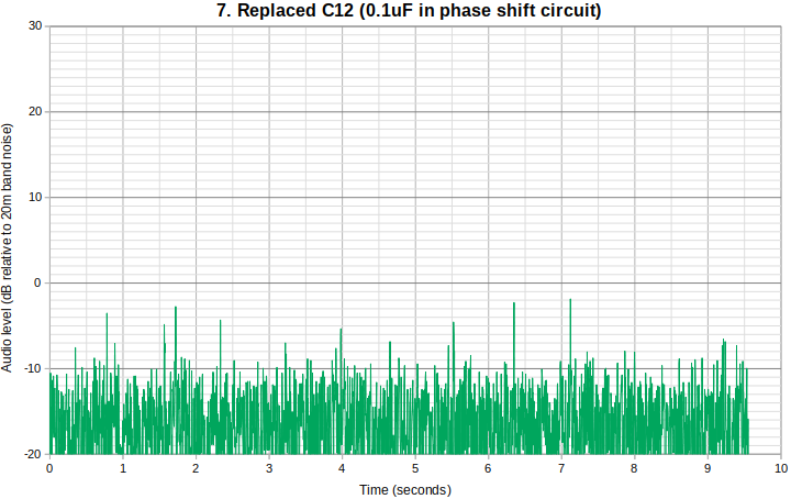
Experiment 7: also replace C12 (0.1uF in the phase shift circuit)
C12 was identified next and replaced. The measurement improved to -2dB, a major improvement, and the pops are now below the -20dBu level of the band noise for the first time! But still detectable (on dummy load).
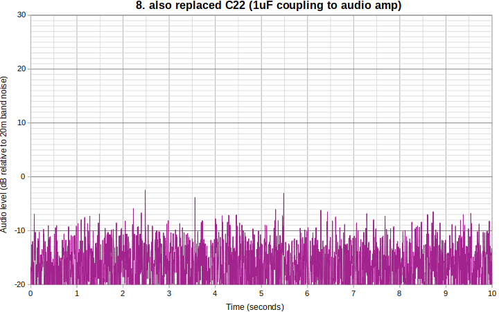
Experiment 8: also replace C22 (1uF)
C22 (1uF) is a DC-blocking capacitor at the input to the final audio amp. It's found to be microphonic by my "scratchy" test with the ceramic screwdriver. Replacing it with the through-hole component produced a further decrease in pop level, to -3dB peak.
Experiment 9: also replaced C21 (1uF)
C21, the other coupling capacitor in the audio chain, that feeds the gain control, was also found to be microphonic. Replacing it produced a further small improvement.
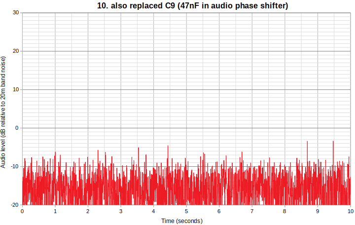
Experiment 10: also replacing C9 (47nF)
C9 is one more capacitor in the audio phase shift network and was also noticeably microphonic. The peak is still -3dB but when you look at the graph below it's very difficult to determine where the button presses are. Audibly with headphones it's also very difficult.
Conclusion and next steps...
The experimental method is no doubt not perfect, with several approximations - but I think good enough to be able to quantitatively track the progress of the improvements as different remedies were tested. Summary of experimental results:
| Experiment | Pop noise (dB over 20m band noise) |
Comments |
| 1. Base case (unmod QCX-mini) | +28 | |
| 2. Play-doh on the QSD capacitors | +23 | unexpected improvement of 5dB relative to base case! |
| 3. Pressure applied with screwdriver | +25 | Minor improvement |
| 4. Silicone pads either side of pillar | +27 | NO improvement |
| 5. Replaced four QSD capacitors | +10 | Big improvement! Greatly reduces the pops |
| 6. also replace C11 (0.47uF) | +9 | |
| 7. also replace C12 (0.1uF) | -2 | |
| 8. also replace C22 (1uF) | -3 | |
| 9. also replace C21 (1uF) | -3 | Small improvement in peaks, lower averages |
| 10. also replace C9 (47nF) | -3 | Same peak but lower averages and hard to hear/see pops |
Replacing these 9 capacitors with their through-hole counterparts apparently is the solution to the microphony problems. The microphony was reduced by an estimated 31dB by these changes.
Even on the dummy load, it is now totally impossible to hear any audible "pop" from pressing the normal push-buttons, and turning the rotary encoder doesn't generate any clicking; the largest pop was always when pressing the shaft of the rotary encoder.
I think it is still just about be possible to hear a microphonic pop when pressing the shaft encoder button but it's hard to know whether this is coming from the headphones, or from the actual mechanical click of the knob being pressed on the bench in front of me - this is even when using passive sound insulating headphones (Heil Pro-Set 3) and the volume set to mid-way, which is a quite loud setting, and with the dummy load used (which has a noise level 18dB below that of the 20m antenna).
There ARE more capacitors which show microphonic behaviour when scratched with the ceramic screwdriver blade but they are much weaker than these 9 replaced here. Really C43/44/45/46, and C11 and C12 make the most difference. I don't think it is necessary to replace any more than these 9. It should be a good solution to the microphony problem. One has to stop somewhere, replacing all the SMD capacitors with through-hole equivalents would be overkill and probably there isn't enough room. In particular, C10 (10nF), C14/16/18 (1nF) and C19/C20 (2.2nF) all show some low levels of microphony but these are much smaller values; for good measure I can use NP0 capacitors at these locations without terrible expense.

This photograph above (click for larger version) shows 8 of the capacitors which are on the underside of the PCB (which is upside-down in the photo); the 9th capacitor is on the other side. So the task now, is to try to move things around to make space for these 9 through-hole components, which take up much more room than the 0603 SMD components they are replacing.
This is the before (blue) and after (red) situation, 10 button presses during a 10 second interval. Note that the 10 button presses don't line up at the same time, of course... in fact in the button presses can't even be seen on the red (after capacitor replacement) line.
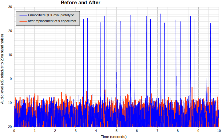
Now the PCB redesign work...