UPDATE 02-May-2025: QMX SSB functionality has now been promoted to official version 1_02_000
Introduction
This is the beta release page for the SSB firmware for QMX/QMX+ transceivers. This is a very complex project. The beta release here is provided without warranty, for brave beta testers who wish to try out the firmware and report back on any issues found or suggested enhancements. The firmware runs on both QMX and QMX+; for convenience from now on, this page will state "QMX" but that means equivalently QMX or QMX+ unless otherwise stated.
Note that users of FSK Digi modes such as FT8, JS8, WSPR, etc should continue to use the QMX "Digi" mode, which will offer the best performance for these modes.
This page describes all aspects of how to use and test this beta firmware for SSB. There are a large number of settings and options and I encourage you to read all the details before experimenting with them. With ALL features enabled (CESSB, compression, mic AGC, Transmit equalization, noise gate, phase and amplitude pre-distortion, you name it), the CPU utilization is approximately 93%. So in other words there is no problem enabling everything.
After a period of beta testing, the firmware will be published to the regular QMX page, and the regular QMX operating manual will be updated to reflect all the changes for SSB. Eventually I will publish extensive technical documentation describing the entire system in detail.
Download
The SSB firmware download is firmware version 1_01_009 and can be downloaded by clicking the link below. The installation procedure is the same as for any other QMX firmware version (refer to manual). Re-calibration is NOT necessary after installing a firmware update.
Firmware 1_01_009 SSB Beta DOWNLOAD
The full version history of changes during the SSB beta testing phase are at the bottom of this page.
Microphone choice
IMPORTANT NOTES ON CHOICE OF MICROPHONE
QMX is designed to use an electret microphone. There is an on-board microphone and an external microphone may be plugged into the Paddle port of the QMX. Currently the built-in onboard electret microphone is not enabled. An external electret microphone must be used currently. All subsequent references to "the microphone" on this page, refer to a plugged-in external microphone. (Audio can also be streamed from the USB audio soundcard from a PC, more on this later).
All electret microphones are NOT alike, in terms of sensitivity and dynamic range. Furthermore if a microphone is used without any kind of windsock to shield it from your breath, there will be a lot of crackles and pops at very low audio frequencies, which will impact speech quality. Electret microphones require a supply voltage which is derived, in the case of QMX, from the 3.3V Vdd supply rail via 2.2K resistor R218. This value 2.2K might not be suitable for all electret microphones, some experimentation is likely to be required.
All development has been done with this particular Electret microphone from Digikey, part number 668-AOM-5024L-HD-F-R-ND:
https://www.digikey.com/en/products/detail/pui-audio-inc/AOM-5024L-HD-F-R/12152286
This is NOT the same microphone as the QMX supplied onboard microphone. Many thanks to Paul W9PEM who gifted me this microphone, beautifully enclosed with a PTT button and 3D printed enclosure.
The QMX SSB firmware contains a microphone testing tool which can be used to establish an appropriate microphone gain setting for your particular microphone. More on this, below.
Microphone Connection:
The microphone is plugged into the QMX Paddle port; this stereo 3.5mm jack plug is for both the microphone signal AND the PTT switch.
- Ring-to-ground is the microphone connection
- Tip-to-ground is for PTT (close the connection tip-to-ground to initiate transmiussion)
Polar Modulation SSB background
Like many things, this deserves a much more thorough write-up. For now just a brief summary which will explain the way SSB is being generated in QMX, with some links to further reading.
Conventional SSB exciters have an SSB modulator (whether done in analog circuits or using SDR techniques) followed by a linear driver amplifier and a linear power amplifier. The linearity is critical to the performance; non-linearities cause intermodulation products which produce close-in spurious products outside the desired SSB passband, causing interference to other spectrum users (known as "Splatter"). The design of the amplifiers needs a lot of care and attention, and the problem is multiplied when a multi-band unit is targeted. It is difficult to achieve good linearity. l
In 1952 Kahn proposed in an IEEE paper, an SSB generation method called EER (Envelope Elimination and Restoration). You can download his paper here. In his paper Kahn describes splitting the SSB process into phase and amplitude components. Phase modulation and amplitude modulation are applied separately. The phase modulated signal is amplified to full power by a non-linear RF amplifier (such as Class-C); then an amplitude modulator is applied to the supply of the RF amplifier to effect the amplitude modulation. The main benefit of this approach is higher performance because RF amplifier linearity ceases to be an issue. Much is made subsequently of the higher efficiency of such amplifiers but it should be noted that obtaining higher efficiency would require high efficiency amplitude modulation also (perhaps using PWM switching techniques).
This paper https://oa.upm.es/7900/2/INVE_MEM_2010_79469.pdf further explores high efficiency techniques for modulating amplitude using multi-level converters for the amplitude envelope amplifier. But this paper is not really so relevant here as it does not deal so much with EER itself.
EER implementations seem to start off with an existing SSB signal, then strip off its amplitude, detect the phase, and apply phase and amplitude modulation as two separate paths. It's debatable whether this is exactly comparable to what is going on in QMX. In QMX audio baseband signals are converted to polar coordinates (phase angle and magnitude), which are then modulated; the phase modulation is applied by a series of rapid frequency updates to the MS5351M and the amplitude modulation is applied in the conventional way by modulating the supply voltage to the non-linear amplifier. "Polar Modulation" is a term that I think I prefer to EER, in the QMX context. Though you could argue that the microphone audio signal is equivalent to an SSB signal at baseband (zero carrier frequency) so you are still eliminating and restoring its envelope...
In 2017 Brian K1LI and Tony K1KP published a QEX article "The Polar Explorer" see https://www.arrl.org/files/file/QEX_Next_Issue/Mar-Apr2017/MBF.pdf describing the design of a high power SSB transmitter using Polar Modulation (EER) techniques. A 500W version of the transmitter was exhibited at Dayton hamvention in 2019 and I had the opportunity to see it for myself. This was my first introduction to Polar Modulation (EER). The article is very interesting; of particular note the phase pre-distortion technique and amplitude pre-distortion employed in the transmitter. The article describes construction of a lookup table for the phase error using an AD8302 gain and phase detector chip - At Digikey even in 2500pcs reel quantity the price is still $18.68 + taxes, OUCH! I am particularly proud of developing a way in QMX to measure the phase error without any additional hardware.
In 2019 Guido PE1NNZ presented his special firmware and extensive hardware modifications to the QRP Labs QCX transceiver to turn it into a multiband SSB transceiver using Polar Modulation (EER). This was a derivative work on his earlier (2013) project to generate SSB directly using a Raspberry Pi, see https://www.pe1nnz.nl.eu.org/2013/05/direct-ssb-generation-on-pll.html. The QCX-derived SSB transceiver spun off into its own separate project, separate forum. The original page is here: https://www.pe1nnz.nl.eu.org/2013/05/direct-ssb-generation-on-pll.html. Subsequently there was a lot of development work done by Guido PE1NNZ, Barb WB2CBA, Manuel DL2MAN and others. Several Chinese produced versions of uSDX are very popular and still in production, as well as an "official" version named (tr)uSDX by Guido PE1NNZ and Manuel DL2MAN see https://dl2man.de/.
The uSDX/(tr)uSDX transceivers suffer significant performance limitations due to the very minimalist hardware used, including the 8-bit 20MHz ATmega328 AVR microcontroller. Pascal VK2IHL has a very long and interesting page https://vk2ihl.wordpress.com/ with many details and measurements. QMX achieves a much higher performance due to the investment in much more powerful hardware (32-bit 168 MHz ARM Cortex M4 MPU with floating point and DSP units). This is not a criticism of uSDX, these are simply engineering trade-offs.
Despite the performance limitations, we owe Guido PE1NNZ a huge debt of gratitude for popularizing and further developing the Polar Modulation concept, demonstrating its practical implementation in minimalist hardware. It's a genius work that is the inspiration behind the QMX SSB firmware implementation. Guido is the giant whose shoulders I stand on.
Dave M0JTS has recently written extensively about the Polar Modulation process, including theoretical explorations, simulations, and experimental determination of the frequency settling time of the Si5351A. His work is a very interesting read, see https://daveshacks.blogspot.com/2025/02
Features
The QMX firmware development contains a rich list of features. These are highly configurable via parameters in the SSB sub-menu (available on both the terminal login and the LCD/buttons of QMX itself).
- Audio equalization applied to microphone signal path.
- Microphone AGC to adjust relatively slowly, the audio level as you may have the microphone closer or further from your mouth.
- Compression.
- Built-in Two-tone test signal generator, adding to the list of built-in test equipment in QMX.
- Audio may be sourced from the internal 48ksps USB sound card for non-FSK Digi modes.
- Controlled Envelope SSB (CESSB).
- Look-ahead Automatic Level Control (ALC).
- DPD (Digital Predistortion) via static phase pre-distortion vector per band.
- Self-calibration tool for measuring the QMX PA's own phase distortion.
- Self-calibration tool for optimizing synchronization between Phase and Amplitude Modulation paths.
- Amplitude modulation interpolation to improve performance of the Amplitude Modulator and correlation with phase modulation.
These features are described in subsequent sections of this page.
Signal diagram
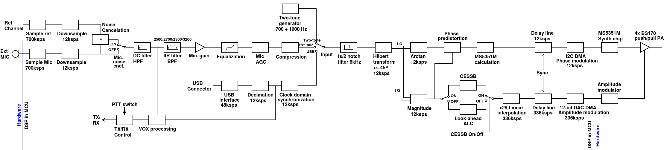
The diagram is probably a bit too small on your screen, you can CLICK HERE to view the original file at full size. Except for the microphone at the left, and the MS5351M, amplifier and PA blocks on the right, this diagram shows all the DSP blocks that the signal passes through in the SSB modulator. Other than the VOX processing and TX/RX control blocks indicated, the signal flows from left to right.
Microphone sampling and noise cancellation
The QMX microphone is, for better or for worse, connected directly to an ADC input pin of the STM32 microcontroller, which has three 12-bit mutiplexed ADC peripherals onboard. In order to gain additional microphone sensitivity, the microphone is sampled at a rate of 700 ksps (700,000 samples per second). Downsampling by a factor of 58.333 (700 ksps / 12 ksps) significantly improves sensitivity.
Unfortunately despite the impressive 12-bit resolution, these ADC's were found to be rather noisy. Spurs are found to occur every 500Hz across the audio spectrum. It was found that the noise is highly correlated between different input channels on the same ADC peripheral. Therefore a reference channel is sampled, also at 700 ksps and also downsampled by a factor of 58.33. If noise cancellation is switched on, the reference channel noise signal is subtracted from the microphone signal path, substantially cancelling the noise on the microphone signal. It is recommended that noise cancellation is always switched on.
In the images below, on the left I show the spur measurements vs the factor of reference channel subtracted. On the right, the audio spectrum plot before (blue, no reference channel subtraction) and after (red, with 0.68 x reference channel subtraction). The audio spectrum was made by recording 30 seconds of silence in a quiet room, streamed to the QMX USB sound card and recorded on the PC in Audacity, which then did the spectrum analysis. The worst spur at 1kHz is reduced by about 24dB and other lower spurs are also significantly reduced. Practically the result is that without noise cancellation, these spurious tones are head clearly at low level as background noise under the speech. When noise cancellation is on, no spurious tones are audible at all.


Microphone test tool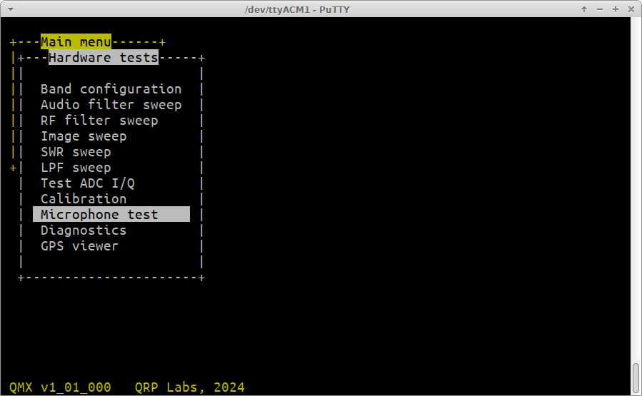
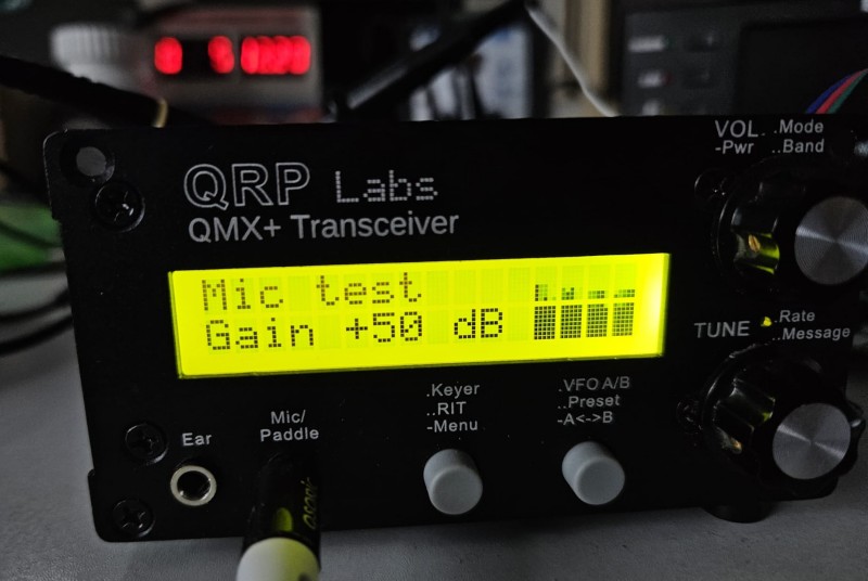
There is a new "Microphone test" screen which allows you to adjust the Microphone gain setting, to suit your particular microphone. The default microphone gain is +50 dB. This tool is in the Hardware tests menu.
When opened on the Terminal:
Press Ctrl-Q to quit
Press R key to Run this test tool
Press + to increase the microphone gain
Press - to decrease the microphone gain
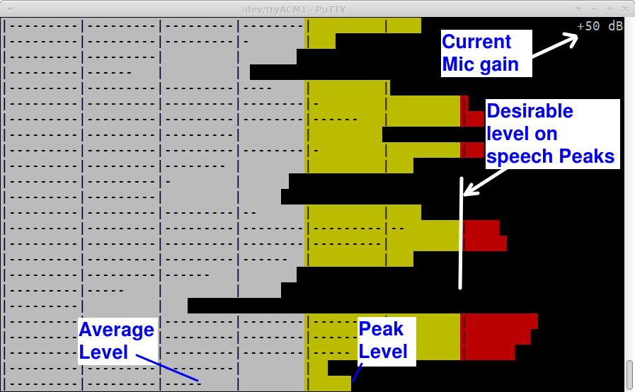
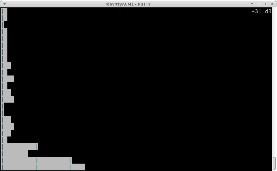
The current microphone gain is shown in the top right corner. When R is pressed to run the application, the screen scrolls up at 10 rows per second. Each row displays the average and peak amplitude from the microphone.
This screenshot shows an annotated explanation:
Notes:
- Current Average Level is on the bottom row, indicated by the horizontal dashes.
- Current Peak Level is on the bottom row, indicated by the extent of the empty bar.
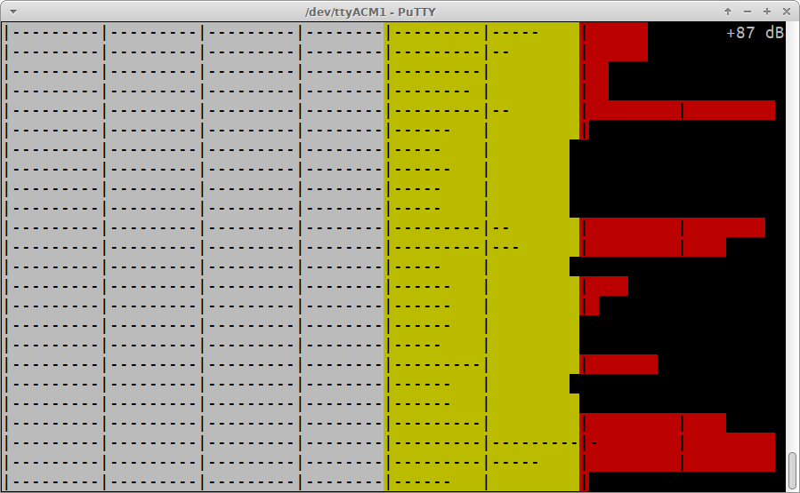
- The current microphone gain is shown in the top right corner; 50dB is the default value and is found to be about right for my microphone (see details of my microphone, above).
- There's a vertical line character for every 10dB of audio signal level.
If you start talking into the microphone at a comfortable distance (don't EAT the microphone, that will result in a lot of whooshing air sounds) and in your normal voice (yes, believe me I know, as soon as you start to sound "normal" you cant't help starting to sound very very UN-normal) - then the gain is kind of correct, or in other words at the correct desirable level, when your speech peaks just starts tipping over into the RED region.
BUT - don't over-fuss it. There are lots more opportunities further down the signal path, for Automatic Gain Control (AGC), Compression, CESSB, etc. It isn't critical, but it helps the subsequent audio processing to get this microphone gain approximately correct, at the start.
IF:
- The gain can't be adjusted high enough - OR -
- The gain is still too high even when you adjust it to minimum - OR -
- If when you're very quiet, compared to the "desirable level" when you speak at the yellow/red sort of level, you don't have about 50dB difference in signal level
then your microphone may not be sensitive enough, or may not have enough dynamic range, or it may need a different value for R218.
Spring has sprung, the lab windows here in the vaulted heights of QRP Labs towers are open and birdsong can be heard. The oscilloscope hums in the background but the QRP Labs elves have gone home for the day. Somewhere overhead a Cessna 172 engine can faintly be heard circling over the lake, no doubt student pilots in training from the local airport flight school. The microphone is lying on the bench and I try to be quiet. This is what my ambient noise level looks like. The little spike at the bottom was when it heard me press the "PRTSC" key on my keyboard (print screen) to take the screenshot.
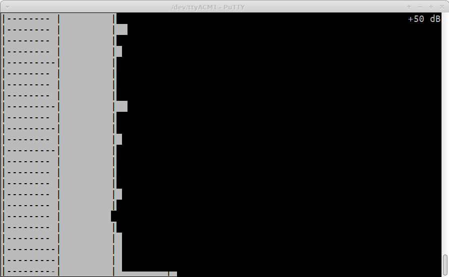
If it's like this, my mic gain is way too low:
And if it's like this, my mic gain is way too high:
And guess what, you can even run this MicTest tool on the LCD screen, how cool is that? In this case the level meter is drawn as a 20 columns by 16-pixel high chart that scrolls across in a left-ward direction, on the right-most 4 x 2 characters of the LCD, at 10 columns per second (so the display shows the last 2 seconds. Use the tune button to adjust the gain such that on speech peaks, the pixels nearly reach the top of the display but don't tend to overdo it.
Other audio sources
USB: When the USB Sound card is selected as the transmit SSB audio source, the Audio is taken from the PC. In this case, as per the DSP block diagram above, No equalization, AGC or Compression is applied to the audio signal. The USB from the PC is expected to be at "full amplitude" which means for most Digi mode software which transmits on a 48ksps, 16-bit basis, the audio is a level numerically between -32767 and + 32768. Transmit/Receive switchover can be achieved either by VOX or using CAT control on QMX's internal USB Virtual COM Serial port in the normal way.
Two-tone: When the two-tone test is selected as the transmit SSB audio source, QMX's internal two-tone test generator is activated. It produces high purity 700 and 1900 Hz sinewaves at 12ksps (which is the internal DSP rate of the SSB generation), summed to full Peak Envelope Power. Press the PTT switch to enable the two-tone transmission (or press the T key when in the SSB configuration screen - more on this later).
Calibration
The next important step to undertake is calibration of your QMX/QMX+ for accurate generation of SSB. Each QMX is different (component tolerances, build-style etc). There are three phases to the calibration:
- Phase distortion measurement for the DPD (Digital Predistortion) phase pre-distortion tables
- Synchronization timing parameter for Phase and Amplitude modulation in USB (upper sideband) mode
- Synchronization timing parameter for Phase and Amplitude modulation in LSB (lower sideband) mode
I have developed a way for QMX to measure its own phase distortion (phase delay at various different output amplitudes, through the PA). Ideally the phase delay through the PA would not vary but it does, most probably as the transistor characteristics vary depending on signal amplitude (such as reverse capacitance of the MOSFET body diode, which is like a varactor diode). This is a very interesting topic but will be a large technical description in its own right.
I also developed a way for QMX to measure its own intermodulation performance, and to optimize the delay line offset between the phase and amplitude paths so as to minimize the sum total of the intermodulation energy in the 3rd, 5th and 7th intermodulation products. Again, ti's a very interesting topic which I will leave to a later time.
For now: a DUMMY LOAD must be connected to QMX for this calibration, both to prevent transmitting power into an open load during the characterization of the PA, and to ensure accurate measurement.
The Transmitter drive level should also be decided at this point. For now, I recommend leaving it at the default level of 900. The maximum level of 999 will mean that the SSB modulator will try to drive the DAC output voltage to a maximum level equivalent to the measured DC supply voltage during receive. This will result in overdriving the SSB exciter and power amplifier since:
- There is a little voltage drop in the power amplifier amplitude modulator itself
- There is some voltage drop in the reverse polarity protection circuits, and perhaps some droop in the power supply during transmit, or drop of voltage on the power supply cabling.
Golden rule: don't push for maximum smoke, it just isn't worth it pushing for that last fraction of a dB of power output, which nobody at the other end of the contact will notice and which really doesn't matter, but puts additional stress on your PA (or at least, reduces the safety margin you have); and in this case, if the SSB exciter and PA are driven to saturation, intermodulation products definitely increase.
I did a particular careful measurement in which I used thick cables from the power supply to the QMX+, on 40m. and I varied the "Drive level" parameter in the configuration from 999 down to 100. The input source was selected as the two-tone test generator producing 700 + 1900Hz sinewave signals internally in the QMX. The graph below plots IMD3 in dP PEP (ARRL style) on the left axis and the Blue curve, and Power in Watts on the right axis in Red curve, vs Drive level along the X-axis.
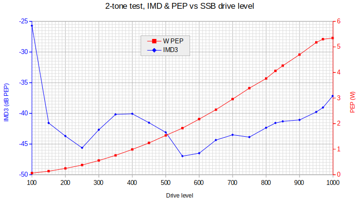
You can see that a drive level of 950 gives an IMD3 fo about -40dB PEPand around 5W PEP. Wind it back to 900, for a bit of safety margin and we get a little improvement in IMD3 and a little lower power outout. This is a setting (I'll come to below) in the SSB configuration parameters menu. It defaults to 900 so why not leave it at 900 for now.
CALIBRATION TOOL
Now the actual calibration tool is in the Hardware Tests menu again. When you open it in the Terminal, you can use the +/- keys to scroll through the existing configuration measurements. You don't see much on a fresh SSB-QMX until the calibration has been performed.
Calibration does take quite some minutes. These are sensitive and difficult measurements for the QMX to perform on itself, requiring some setup time, stabilization time then measurement time with multiple measurement averaging. This calibration need only be done once for each QMX but if you did a factory reset you would need to re-do it.
With no calibration at all, your QMX SSB performance would still be pretty reasonable! But measured phase pre-distortion curves and optimum synchronization of the delay lines to match up phase and amplitude modulation, do really make a noticeable difference.
As you press the +/- keys to go through the calibration, you can run one screen on its own if you wish, by pressing the 'O' key. If you want to run all the calibrations, press the R key. It starts with the phase distortion measurement, and runs it for each band in your Band Configuration. Then Upper sideband (USB) sync optimization for each band, then Lower sideband (LSB) sync optimization for each band.
During the calibration, the measurements are displayed on the bottom row of the terminal screen and the graph is plotted point by point. At the end of the measurement the values are rescaled and optimized for storage; the graph limits and scale changes but the values are unaltered.
The results are markedly different by band, this is normal. The images in the gallery below (click them) show some examples of phase distortion measurement curves and sync optimization curves. The calibration tool can also be run from the QMX itself, of course the graph displayed on the tiny pixel mapped display is less clear. The results however are identical. On the LCD version of the calibration application, use the "Tune" knob to view existing calibration curves; press the "Tune" knob button to run ONE calibration or press the left push-button (menu button) to run all calibrations.


I have a "Reference" QMX+ PCB Rev3 which is unmodified, unmutilated, and otherwise in happy condition. It is connected to a Pi400 and runs 24x7 on JS8 or sometimes WSPR or whatever else I wish to use it for. The gallery below shows the complete calibration result, 36 images (Phase, USB sync, LSB sync for all 12 bands). Some phase error measurements do have weird glitches. Reasonable information from 160m (which still has receiver clock phase quadrature problems) is not expected. Some other bands have glitches on the phase distortion measurement too. Bear in mind that there could be spurious responses involved and this is also the fact for the Synchronization optimization. The y-axis indicates the total energy measured in the 3'rd, 5'th and 7'th order intermodulation products; the y-axis units are relative only. A spur in the passband would add a fixed amount that elevates any observable dip, but would not necessarily indicate problems.


Menu re-organization
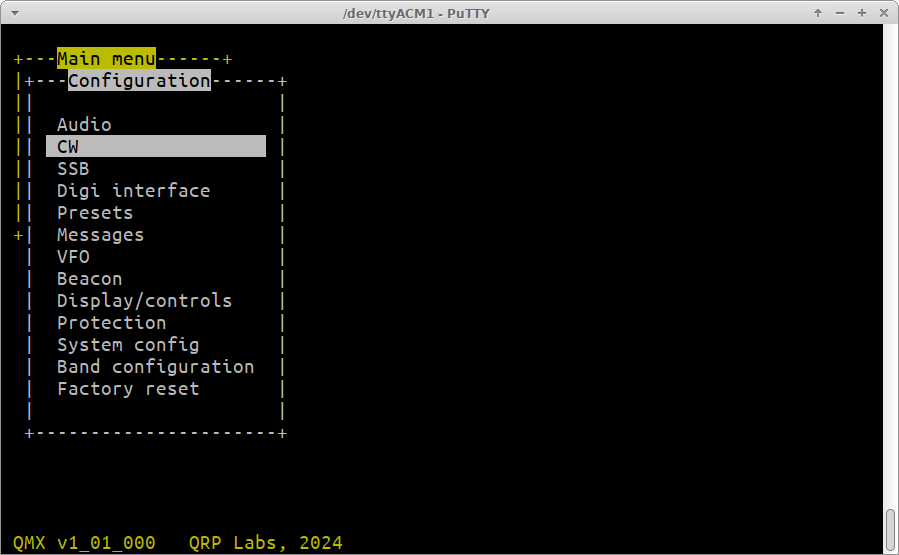
The QMX menu was inherited from the QCX menu system. QCX is a single band, CW-only transceiver. QMX is a much more capable, multi-band and multi-mode transceiver. I thought that it was appropriate rather than extend the length of the top-level menu even more, to instead re-organize slightly. Now everything related to CW (Decoder settings, Keyer settings, Sidetone settings etc) is placed under the CW menu. The new SSB menu contains everything related to SSB.
SSB menu explanation
The SSB menu contains a number of top-level configuration parameters and four sub-menus. Every aspect of the SSB exciter can be controlled by these menu parameters. At the moment there are probably TOO many menu parameters, some may never need to be changed and perhaps could later be hidden, or moved into an "Advanced settings" menu. For now, they are all exposed in order to facilitate testing.
NOTE: Unlike many of the configuration parameters in QMX, the SSB configuration menu items take effect as soon as you edit them; and you can transmit while you are inside the configuration menu. This allows you to experiment with settings until you find your favorite operating conditions, without having to keep leaving the menu to test, then re-enter. You may also, in the main SSB menu when in the terminal, press the 'T' key to toggle transmission on or off. Which allows some testing even if you don't have a PTT switch plugged in.
This page is written assuming the use of the terminal interface, but all of the configuration menus are also available equivalently on the QMX itself via the LCD and buttons, in the normal way.
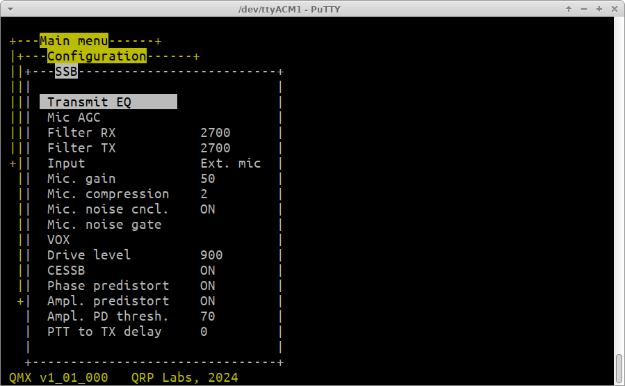
I'll deal with the menu options just simply from top to bottom.
Transmit EQ
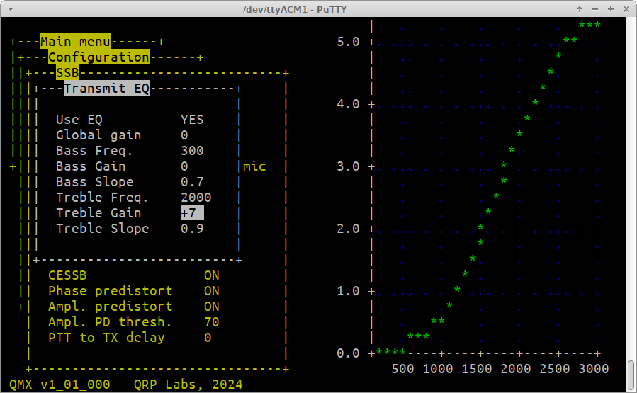
The Transmit EQ screen contains configuration settings for a parametric equalizer. There are two filters, for bass and treble response; this type of filter is called a Biquad shelf filter. The configuration settings determine the parameters used to calculate the shelf filter coefficients. There's a visualization of the response of the filter, which is updated almost in real time around one second after a parameter is changed. The parameters can also be edited on the LCD, and s miniature version of the response curve is plotted on the right side of the display.
Note that many DX experts recommend that a large amount of energy is concentrated in the bass parts of human speech, but this contributes very little to the intelligibility of the transmission. It is therefore recommended to boost the treble end of the speech spectrum and attenuate the bass end.
Use EQ: Use the left and right buttons to choose YES or NO, to enable or disable the Transmit Equalization.
Global gain: This is a gain in dB which is applied to the entire curve. You can use it for example, if you have specified coefficients for the rest of the curve which involve negative gains, if you wish to bring up the level to an overall average zero level. Or vice versa. The global gain parameter has values from -20 dB to +20 dB in 1dB steps and you press the left or right arrow buttons to increase or decrease the chosen gain.
Bass Freq: The low shelf mid-point frequency. This is the frequency where the gain is 0.5 of the total configured gain for the shelf. In the above example, the bass filter is not being used (gain is zero); but the treble filter has a "frequency", the mid-point frequency, of 2000 Hz; and the Treble Gain is +7 dB. This means that the gain at 2000 Hz will be half, which is 3.5 dB. If you examine the curve in the screenshot above, you can see that indeed this is the case.
Bass Gain: The total gain of the low shelf filter. This is the gain which the filter would eventually reach at zero frequency. This gain parameter has values from -20 dB to +20 dB in 1dB steps and you press the left or right arrow buttons to increase or decrease the chosen gain.
Bass Slope: A measure of the steepness of the slope. The slope parameter has values from 0.0 to 2.0 in steps of 0.1 and you press the left or right arrow buttons to increase or decrease the slope. Note that for very steep slopes > 1.0, the response will slightly overshoot the x-axis (zero).
Treble Freq: The high shelf mid-point frequency. This is the frequency where the gain is 0.5 of the total configured gain for the shelf. In the above example, the bass filter is not being used (gain is zero); but the treble filter has a "frequency", the mid-point frequency, of 2000 Hz; and the Treble Gain is +7 dB. This means that the gain at 2000 Hz will be half, which is 3.5 dB. If you examine the curve in the screenshot above, you can see that indeed this is the case.
Treble Gain: The total gain of the low shelf filter. This is the gain which the filter would eventually reach at high frequencies way beyond the shelf mid-point frequency. This gain parameter has values from -20 dB to +20 dB in 1dB steps and you press the left or right arrow buttons to increase or decrease the chosen gain.
Treble Slope: A measure of the steepness of the slope. The slope parameter has values from 0.0 to 2.0 in steps of 0.1 and you press the left or right arrow buttons to increase or decrease the slope. Note that for very steep slopes > 1.0, the response will slightly overshoot the x-axis (zero).
Mic AGC
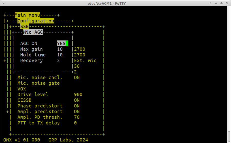
This screen controls the microphone AGC. It is intended as a slow automatic gain control to adjust the gain to compensate for you moving further or closer to the microphone, or variations in your speech volume, etc. It's not the same thing as compression. Effectively this is a simplified, fast version of the AGC system used for the Receiver.
AGC ON: Use the left and right buttons to choose YES or NO, to enable or disable the AGC.
Max gain: The maximum gain of this AGC system, expressed in dB. The gain is varied by the AGC system, from this max gain value, to zero. To initialize the system, the max gain is applied to the microphone signal for a period of 0.01 seconds. The gain is reduced such that the peak audio during this measurement period, equals full scale. From then on, the gain is reduced quickly on speech peaks, and returns slowly to full gain during quieter speech.
Hold time: After reducing the gain (because the gain-adjusted signal would exceed the full scale amplitude), the gain is held at its value for this hold time. The hold time is expressed in tenths of a second.
Recovery: How quickly the gain starts returning to maximum after the hold time expires. This parameter is expressed in dB per second. In the example shown, the max gain is 10 dB and the recovery is 2 dB / second. So for example let us suppose that, in a sudden fit of excitement at hearing a rare DX station, you went from a peaceful quiet human being into a raving maniac and started yelling into the microphone; the AGC gain would be reduced from 10dB to zero; held there for 1 second; then begin recovering back up to 10dB (assuming your yelling had stopped) at 2dB / second taking 5 seconds to reach full 10dB gain.
Back to the main SSB menu
Filter RX: The filter bandwidth used for SSB reception
Filter TX: The filter bandwidth used for SSB transmission; this filter is applied (refer to the signal path diagram above) to the microphone signal early in the processing, right after downsampling, noise cancellation and DC level elimination.
Input: Choose the audio to be routed to the SSB exciter. The three choices are:
- Ext. mic: External microphone plugged into the paddle port
- USB: The QMX built-in USB soundcard receiving audio from a host PC, for example for Digi modes
- Two-tone: Two-tone intermodulation test signal generator within QMX (standard 700 + 1900 Hz tones).
Mic. gain: A fixed gain (in dB) applied to the microphone signal to bring it approximately into the desired range. This is the same parameter which can be adjusted in the Microphone Test screen (refer to above section).
Mic. compression: Compression is a gain factor which increases the average to peak power of the SSB transmission, giving you extra punch in weak signal conditions, DX, contests etc. It is applied to the softer quieter parts of the human speech to make them louder. The loudest peaks are untouched. This compression parameter is specified in dB and nothing stops you from increasing it all the way up to 99dB but that would be utterly ridiculous. It MUST be noted that compression can improve intelligibility but also results in more distorted, less natural sounding speech. So it should be used with caution. I have tried up to 18dB and it was still recognizably me and easy to understand, and much louder.
Mic. noise. cncl.: Use the left and right buttons to choose ON or OFF, to enable or disable the microphone noise cancellation. The noise cancellation technique was discussed further up this page. It is recommended that noise cancellation is always ON.
Mic. noise gate
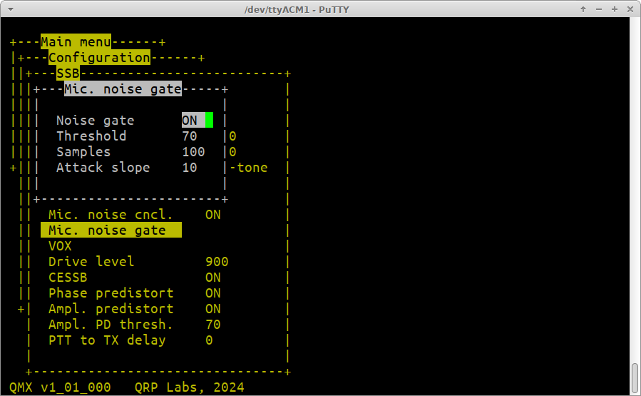
The noise gate is an important parameter to understand. The key issue is the leakage through the PA even when the amplitude voltage is zero. This occurs because in the QMX circuit, the BS170 PA transistor gates are driven with a 5V square wave from 74ACT08 logic gates. The drive signal is present on the BS170 gates even when the Drain voltage is zero (zero amplitude modulation). Some of this signal leaks through the PA transistors in this OFF condition due to their capacitance.
Practically speaking, the Peak-Peak RF output of the PA is extremely linear with respect to the control voltage from the microcontroller's Digital to Analog Converter (DAC) output, from 45 or 50V peak-to-peak (5W is 45Vpp) down to below 1V. But somewhere between 0.5V and 1.0V, even though the DAC value goes to zero, the RF peak-to-peak does not decrease further. The control range is around 37dB of linear straight line control range. Which is good, but not infinite.
Even when the signal coming from the microphone is extremely low, the SSB modulator (polar modulation technique) still tries to convert it to polar coordinate space (angle and magnitude) for transmission as separate phase and amplitude modulation components. Low level microphone noise translates to phase angles that jump around randomly all over the circle. If the amplitude were truly zero, this would not matter. However, as it is, even with 1Vpp you can hear this noise.
This *may* be being FAR too perfectionist. 1Vpp into a 50-ohm system is 2.5 milliWatts. 37dB down from Peak Envelope Power. It was audible to me during testing because I transmitted at 5W PEP from a QMX+ into 79dB of inline BNC attenuators, straight into a QDX acting as the receiver. At the QDX input that results in an S9 + 30dB signal! Meanwhile there is no band noise, because the QDX (as receiver) RF port is piped straight to the QMX+ (as transmitter) RF port via BNC attenuators. 37dB down from Peak Envelope Power still leaves you with an S8 signal, and with a very low noise floor any defects are therefore extremely clear! It's a very very harsh test environment. In real life conditions you would be unlikely to be putting such an enormous signal into the other station's receiver, and he would not have zero band noise and zero other QRM. So these 37dB down defects may not be noticed.
Nevertheless, this menu exists to gate this microphone noise below a chosen threshold. The gate operates by switching off the TX signal to the driver altogether. It needs to be used with care, since there is nothing between zero output and 1Vpp. If the gate opens and closes too often, it produces a scratchy type of sound at low level on the audio, which is quite annoying.
Noise gate: Use the left and right buttons to choose ON or OFF, to enable or disable the noise gate.
Threshold: This is the threshold of operation of the noise gate. It is expressed in DAC units. So it's a voltage parameter (not dB, not power). The DAC output range is 0 to 4095. The DAC voltage is multiplied by the amplitude modulator to a voltage supplied to the PA, by a factor of 6.24. The default threshold 70 therefore corresponds to a PA voltage applied of 6.24 * 3.3 * 70 / 4096 = 0.35V. This is found to be a reasonable value; Vpp is about 3 or 4x the DC supply voltage therefore 0.35V DC supply is above 1Vpp and a suitable threshold.
Samples: A kind of delay mechanism, crudely speaking, which prevents the gate operating too often. Each sample (running at 12ksps) whose envelope DAC value is greater (or equal) than the threshold increases a counter. When the counter reaches this "Samples" value, the transmitter is switched on (MS5351M Clk2 oscillator signal is allowed to drive the BS170 gate pins via the 74ACT08 logic gate). Subsequently for each sample whose envelope DAC value is less than the threshold, the internal counter is decreased by 1. When it reaches zero, the transmitter is switched OFF by disabling the driver. In this way, samples slows down the gating, creating a kind of hysteresis which prevents rapid crackling occurring by too many on/off gate actions.
Attack slope: This is a way to ensure the transmitter turns on more quickly than it turns off. While the internal counter is decreased by 1 for each sample whose envelope is below the threshold, it is increased by the "Attack slope" value for each sample whose envelope value is greater (or equal) than the threshold. This makes the intended voice syllables appear more crisp as there is much less delay before the transmitter is switched on.
VOX
VOX means Voice Operating Exchange or more commonly, Voice Operated Transmission. Instead of waiting for a PTT button to be pressed to initiate transmission, the radio monitors the microphone continuously during receive, and if there is a noise it enables the transmitter. In the QMX the audio source can be the USB sound card, so the VOX settings also apply to the USB sound card audio, if USB is selected as the Input source for the SSB transmitter. The VOX subsystem operates in parallel with the PTT button, and indeed the CAT commands. So you can still activate transmission by the PTT button for example, even when VOX is on.
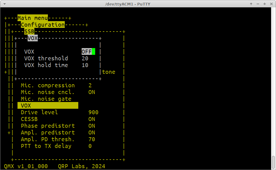
VOX: Use the left and right buttons to choose ON or OFF, to enable or disable the VOX feature.
VOX threshold: This is the threshold amplitude which will trigger transmission when VOX is enabled. This is expressed as the percentage of full scale (for the USB audio). When the microphone is connected, it approximately equates to the percentage of the audio peaks at the microphone input which cause full power transmission. That IS approximate because it doesn't pass through the band pass filter, equalization, compression etc blocks, none of which are active during Receive. This does not appear to matter or diminish the effectiveness of VOX.
VOX hold time: Once the VOX subsystem has triggered transmit, this parameter specifies how many tenths of a second it will remain held in transmit when the microphone audio is below the VOX threshold.
Back to the main SSB menu
Drive level: This specifies the maximum drive level to the amplitude modulator as a function of the measured input supply voltage (as measured during Receive). This was also discussed further up this page. If this drive level is too high, clipping of the RF waveform will occur which cannot be prevented by CESSB, ALC or any other mechanism, since all those mechanisms DEPEND on this drive level, to determine what level of audio to allow through to the PA. The amplitude modulator circuit itself has some loss voltage; and the reverse polarity protection circuit also has a small voltage drop; furthermore the supply cables may have a voltage drop between Receive and the 10x higher current draw during transmit. If the level is too high, the intermodulation performance will deteriorate. The default value of 900 is usually a reasonable compromise in the absence of measurements.
CESSB: Use the left and right buttons to choose ON or OFF, to enable or disable the CESSB feature.
Controlled Envelope SSB is a way of removing the amplitude envelope overshoots which occur in all SSB transmitters. CESSB was introduced by David Hershberger W9GER in a 2014 QEX article: http://www.arrl.org/files/file/QEX_Next_Issue/2014/Nov-Dec_2014/Hershberger_QEX_11_14.pdf. This article explains everything. It is vital to understand that SSB amplitude envelope is NOT a problem specific to Digital (SDR) SSB transmitters. It occurs on ANY SSB transmitter, whether an old filter-method SSB tranceiver, phasing analog transceiver, Weaver, ANYTHING.
The effect of having CESSB switched ON, on speech, is typically to increase the effective power of the transmitter by around 4 to 5 dB. So a 5W transmitter will sound to the remote station as though it is running 12W (for example). For single tone (CW), two-tone transmissions, FSK Digi modes, and some others, CESSB does not provide any improvement. It is primarily a technique for improving average to peak power on Speech transmissions.
If CESSB is not switched on, in QMX (and in other transceivers), Automatic Level Control (ALC) will act to reduce the gain of the transmitter, to prevent the overshooting peaks of the amplitude envelope from driving the PA into highly non-linear clipping. It is reported that the very best, fast look-ahead ALC systems can produce an improvement of around 2dB. So CESSB is still a clear winner compared to excellent ALC.
In QMX, when CESSB is switched off, a simple ALC action is implemented which prevents peaks from causing RF clipping and temporarily reduces gain, which is held at the lower value and gradually recovers; in very much the same way as the Microphone AGC described above.
It is recommended that in QMX, CESSB be left switched ON.
Phase predistort: Use the left and right buttons to choose ON or OFF, to enable or disable the Phase pre-distortion feature.
When ON, each phase modulation sample is adjusted to cancel out phase distortion in the PA. Phase distortion occurs when there is a variable phase shift depending on the amplitude of the signal. This occurs because of changes in the transistor characteristics depending on Drain voltage; for example, the body diode acts as a reverse biased varactor diode whose capacitance is less when the applied voltage is higher.
QMX stores a phase pre-distortion curve of phase error vs amplitude, for each band of operation. These curves are measured by QMX using the Calibration tool described earlier in this page. If Phase pre-distortion is ON and Calibration has not been run, it will have no effect (because the calibration curves are zero).
When used correctly, phase pre-distortion makes a significant improvement to intermodulation performance.
Ampl. predistort: Use the left and right buttons to choose ON or OFF, to enable or disable the Amplitude pre-distortion feature.
The huge advantage of polar modulation generated SSB is that it does not rely for its performance, on the amplitude linearity of an RF amplifier. Instead, there are separate phase modulation and amplitude modulation signal paths. The amplitude modulation does need to have high linearity. Howewer, this is very much easier to achieve by the use of more complex, multi-device feedback amplifiers, because the amplitude modulation occurs at audio frequencies.
In the section above regarding Microphone noise gating, I described a limitation of the amplitude modulator circuit. Even at zero amplitude, some blow-by of signal occurs and there is around 1Vpp output RF, when there should be zero. This limits the control range of the amplifier to about 0.5Vpp to 50Vpp, a control range of about 37 dB.
A slight improvement in intermodulation performance is just about observable, by switching off the transmit signal altogether at amplitudes below about 1Vpp. I am calling this "Amplitude pre-distortion", though it is really a very crude action to try to correct this low amplitude misbehaviour. Although switching off the transmission completely is a quite approximate tool, it does appear to make a marginal difference to the two-tone intermodulation performance.
Whether or not it is of significant benefit in ordinary speech transmissions, remains to be seen.
In the oscilloscope screenshot gallery below (click for the fullsize images), the two-tone test generator is used as the signal source. The amplitude envelope DAC control signal has a "rectified sinewave" appearance, decreasing to zero at a rate equivalent to the difference in frequency of the tones (1200 Hz in this case).
- Left: Amplitude pre-distortion is switched OFF. You can clearly see that the amplitude envelope does not reach zero, it cannot go lower than about 1Vpp.
- Middle: When Amplitude pre-distortion is switched ON, the transmission is stopped momentarily (for about 20us in this case) while the amplitude is small.
- Right: A zoomed in view of the zero point.


Ampl. PD thresh.: This simply controls the threshold, in DAC steps, at which the Amplitude pre-distortion acts. A value of 70 corresponds approximately to around 1Vpp RF.
PTT to TX delay: A delay in milliseconds, between when PTT is pressed and when transmission actually starts. Correspondingly on releasing the PTT switch to cease transmission, the SSB transmission stops then the system waits this number of milliseconds before switching QMX back to Receive mode.
Two-tone test measurement results
Below are some measurements using the 700 + 1900 Hz two-tone test generator on 40m, to illustrate the effects of switching off phase pre-distortion and amplitude pre-distortion (stopping TX drive at very low amplitudes).
Sidenote regarding IMD units: there are two different systems in operation and it can get confusing. One way of reporting IMD products is to report the level of the spurious responses relative to the desired carrier. In that case the IMD level may be -35 dBc for example (dBc means dB relative to carrier level). The OTHER way is favored by the ARRL in lab measurements in QST reviews (and elsewhere), and expressed intermodulation products relative to PEP (Peak Envelope Power). There is a 6dB difference between the two ways of expressing the same result. So -35 dBc is equal to -41 dB PEP. It doesn't matter which one is used, as long as you are clear on what you mean, and make sure any comparisons you make are all using the same units. I got used to dB PEP so I use that.
In the images below:
Left: Phase and Amplitude pre-distortion OFF. IMD3 is -38.85 dB PEP (note, the specc ann. delta cursor marker measures dBc as it is is set up here, and dB PEP is 6dB less than dBc as I explained above).
Middle: Phase pre-distortion is ON, amplitude pre-distortion is OFF. Showing the significant improvement due to phase pre-distortion. IMD3 is now -39.20 dB PEP but many of the higher order products are significantly lower ampliitude.
Right: Both phase and amplitude pre-distortion are ON. It yields the best IMD3 result, -40.42 dB PEP. Some higher order IMD products are lower, some are higher. It appears to me that on the whole, on average, IMD spurs are lower with amplitude pre-distortion ON. But it makes only a little difference and is hard to judge, whereas phase pre-distortion is a very clear improvement.


Amplitude modulator imperfection
One of the minor imperfections in the hardware occurs in the amplitude modulator, and is well illustrated by this oscilloscope trace photograph I took in August 2024.
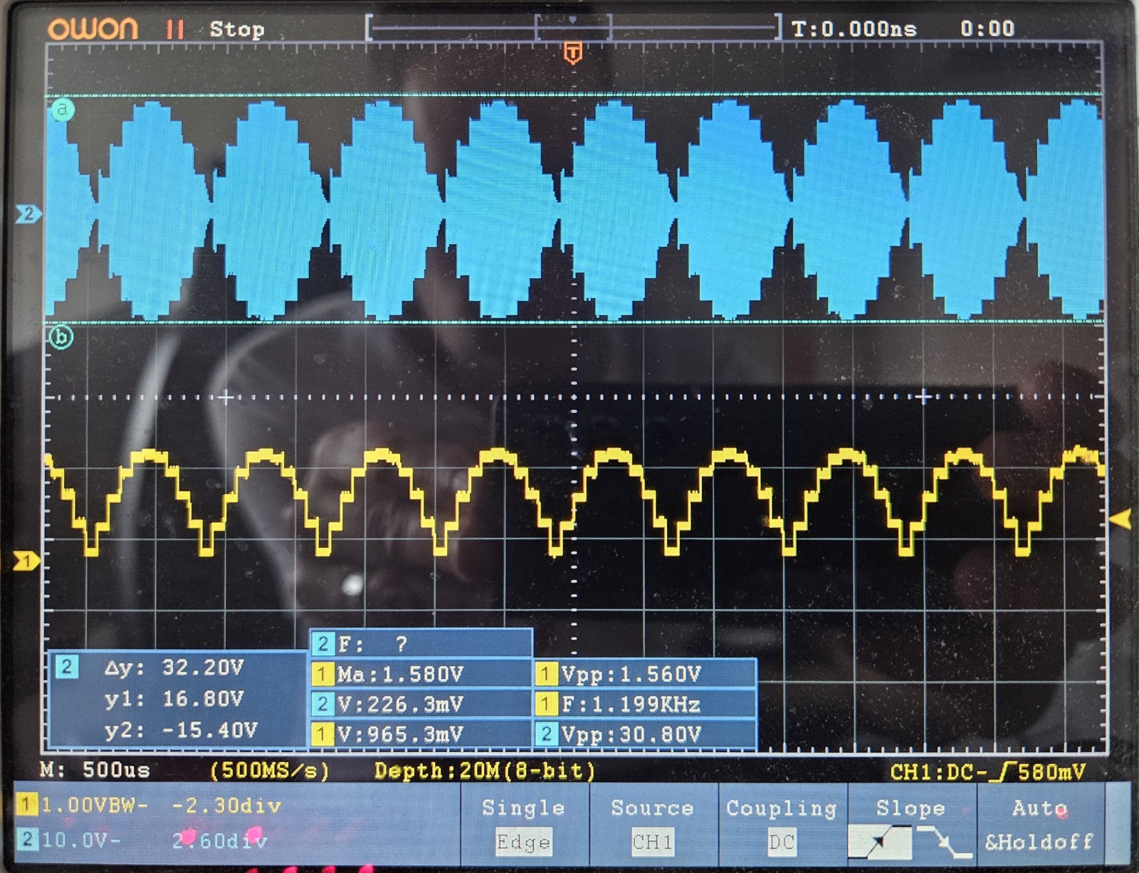
The bottom (yellow) channel at 1V/div shows the DAC output voltage which appears across C503, the input to the amplitude modulator.
The top (blue) channel at 10V/div shows the RF output signal across the dummy load, which in this case is set to about 2.4W PEP.
The signal is the two-tone (700 + 1900 Hz) test. As the DSP runs at 12ksps, this means that the frequency of these half-sine-waves is 1200 Hz (the difference between the tones). The DAC control voltage, +/- noise and RF sloshing around the shack, is a clean staircase of the 10 samples (at 12ksps) which make up every sine half-cycle of the amplitude envelope.
Several defects are identified in the below extract from this image:
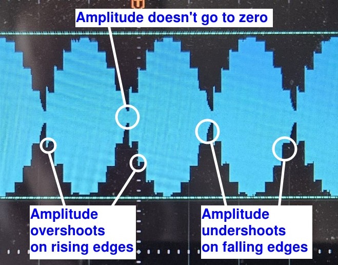
The amplitude not going to zero at the zero amplitude point of the phase reversal is a problem that has already been discussed and was resolved (as well as possible) by the "Amplitude pre-distortion" switch which when ON, causes the transmit signal to be gated off when the target amplitude is below 1Vpp. It makes a small difference to transmitter IMD products (see above).
The other problems are the response time of the amplitude modulator, to the commanded amplitude (per the input from the microcontroller DAC pin). During steps UP in amplitude (rising edge of the waveform) the amplitude is seen to temporarily overshoot the desired step height. And during steps DOWN in amplitude (falling edge of the waveform), the amplitude is seen to too slowly decay to the desired step height rather than reach it immediately. These problems were significantly impairing the IMD performance of the transmissions.
I tried a number of strategies (all in firmware) to address this issue. Note also that the overshoots are most severe when the steps are large. Which is what gave me an idea. I arranged to interpolate (simple straight line linear interpolation) the amplitude envelope samples, adding a "mid point" between each of the actual samples.With the Digital Signal Processing running at a rate of 12ksps, as well as the phase modulation to the MS5351M, this meant that the amplitude modulation was streaming samples to the DAC at a rate of 24ksps. It made a large improvement to the intermodulation products!
So I continued increasing the number of interpolation points, to 4, 8, 16. Each time there was an improvement in IMD but the improvements became smaller and smaller. At the point I went from 32 interpolation points to 64, the system hung up and I wrenched the power supply plug, fearing smoke. For a long time I stuck with 32 but in the end I reduced it to 28, which does not detectably alter performance, because 28 works out with integer divisions from the system clock rate of 168 MHz whereas 32 didn't (and led to discontinuities in the audio sample stream).
The image below shows the final result after interpolation. There are still only 10 actual calculated points per wave cycle (700 + 1900 Hz two-tone at 12ksps). You can see the calculated points and the straight line between them of tiny invisible steps. This completely solved the problems of amplifier over/undershoot.

Firmware version history:
| Version | Date | Contents |
| 1_01_009 | 30-Apr-2025 | 1. More small USB tweaks directed at Win7 2. Bug fix: USB gain not loaded 3. Bug fix: Sync calibration screens display issue (wrote over top of previous cals) 4. Calibration quit and set error vector to zero when cannot be measured |
| 1_01_008 | 29-Apr-2025 | 1. Improvement to synchronization section of the SSB calibration 2. Bug fix: CAT LC; query now includes commas and dots 3. Bug fix: Re-run of PA amplitude modulator test didn't clear the old graph 4. Added USB Gain to SSB configuration menu (gain for audio coming from the USB port) 5. Now remembers previous menu location on ALL menus regardless of nesting level 6. Microphone VOX now works on raw external microphone audio, not including correction from onboard mic 7. Bug fix: If running Calibration and I open another terminal window, it will update in the new window 8. One more minor USB multi-port attempt (directed at Win7) |
| 1_01_007 | 26-Apr-2025 | 1. One more bug fix to USB compound device descriptor, now 3 serial ports works on Windows |
| 1_01_006 | 25-Apr-2025 | 1. Bug fix to USB compound device descriptor, now works on Windows |
| 1_01_005 | 25-Apr-2025 | 1. Improved SSB calibration reliability 2. Added config option to select 1, 2 or 3 Serial COM ports |
| 1_01_004 | 23-Apr-2025 | 1. Bug fix: Incorrect PA voltage display on the Diagnostics screen 2. Change TX color in diagnostics screen from red to blue, to avoid confusion since red things are errors 3. Added two more USB Virtual COM serial ports 4. Added CAT LC command to retrieve LCD contents 5. Added CAT commands SA (AGC meter), SM (S meter), PC (Power meter), SW (SWR meter) 6. Added CAT command SS (get/set SSB input source) 7. LCD versions of AF, RF, Image, LPF, Test ADC I/Q sweeps (miniature graph on LCD) 8. New function PA mod. test to check operation of amplitude modulator 9. Diagnostics screens are now available on the LCD interface too 10. Calibration now tests PA modulator first, and refuses to run if the modulator isn't working 11. Calibration now writes zero phase compensation if a band calibration fails |
| 1_01_003 | 21-Mar-2025 | 1. Bug fix: Initial value for noise gate samples was 100 (should be max 99) 2. Added TX indication underlining the A character when USB transmitting in SSB 3. Bug fix: CAT command TQ1; did not cause transmit when in SSB mode 4. Bug fix: Prevent button presses from accidentally activating VOX 5. Power meter now reads Peak Envelope Power (PEP) when in SSB mode 6. Bug fixL Calibration hung at DAC 1300 when run on LCD |
| 1_01_002 | 20-Mar-2025 | 1. Bug fix: Update year to 2025 on terminal and LCD splash screen 2. Bug fix: Incorrect percentage completion status in phase error Calibration 3. Bug fix: Changes to SSB drive level did not take effect until leaving config 4. Bug fix: SWR protection was enabled in SSB even when SWR was disabled in menu! 5. Bug fix: CW memory keying activated with Tune DblClick during SSB mode 6. Bug fix: Hardware tests / Audio sweep wasn't working 7. Bug fix: Lockup when entering VFO modes menu on terminal |
| 1_01_001 | 19-Mar-2025 | 1. Bug fix: CAT TX; command was not working for PTT controlled from a computer. 2. Bug fix: SWR protection was not working for SSB modes. 3. Added delay between phase distortion calibration steps (delay milliseconds = DAC, when above 1200). |
| 1_01_000 | 18-Mar-2025 | 1. Initial beta firmware release of SSB firmware. 2. Bug fix: Positive acting PTT output was not working properly (not completely switched ON). 3. Added a way of forcing a factory reset during power up by pressing press left (menu) button during power up. 4. Menu reorganization and new menu items as listed on this page. |
SSB success stories
There are of course plenty of observations, bug reports, suggestions for improvements about the SSB firmware. However I feel it is worth including here some of the stories of successful operations using SSB.
Jack KD4IZ: Kudos to Hans - the beta was well worth the wait!
Thanks again to the folks that helped me earlier this year locate and replace the bad switch. I had not used the little beast that much after confirming the repair, mostly due to time commitments. Did get some good reports on CW, then shelved it until firmware beta 1-01-003 that covered SSB was dropped.
The firmware upgrade was straight forward. I constructed two Mic adapters, one for a spare ICOM HM-219 and one for a Heil ProSet Elite iC. Both worked well without adjustments of any kind.
First voice QSO was this afternoon on 40M with VA3XV up in Ontario (about 400+ miles). He reported the audio to be as very nice, as good as my 7610. The QMX+ even received a 54 sig report when the QSB and adjacent frequency QRM was not present.
Next up configuring it for fldigi - FSQ and other digital modes... and of course portable ops. So far this has proved an excellent and surprisingly full featured little rig.