My QCX is too loud... and the gain potentiometer is Linear, isn't it supposed to be Logarithmic?
Several people have commented that they typically only use the first 10% of the rotation of the QCX audio gain potentiometer; after that it is too loud. People also mentioned that the manual says the potentiometer is a logarithmic one (also known as "audio taper") but the supplied 5K potentiometer is actually Linear.
We prefer Logarithmic for a volume control because this is roughly how our ears perceive loudness.
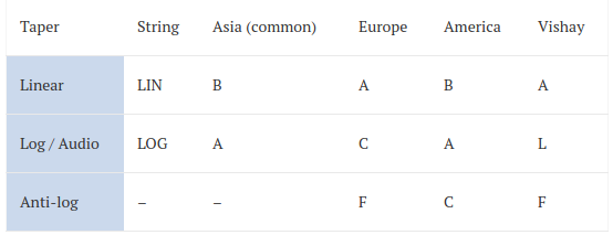
Confusing labels
I grew up thinking, all my life until relatively recently, that a potentiometer labeled A is Linear and a potentiometer labeled B is Logarithmic. So 5KB (as in the QCX) would be 5K logarithmic. It probably actually WAS really like that. But not any more! Or perhaps, in some parts of the world but not others. The most common "standard" now appears to be that A means Log and B means Linear. I think that there are enough old pots and enough confusion that I would never again trust the A or B to tell me anything; best to refer to datasheets or in the case of scavenged (unknown) components, measure them.
The following table from http://www.resistorguide.com/potentiometer-taper/ also confirms this confusion. This page says that the most common "standard" currently in use is the Asian one (A = Log, B = Linear).
"Audio taper" potentiometers
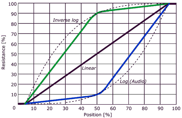
Most "audio taper" potentiometers aren't really logarithmic, they often contain two linear tracks over different parts of the rotation so that they appear reasonably close to logarithmic. "Audio" potentiometers are hard to find and expensive and if it really is a true logarithmic pot then it is even more rare and expensive.
Also from http://www.resistorguide.com/potentiometer-taper/, a graph showing the approximation of an "audio taper" pot having two linear tracks:
At the time of designing the QCX I really thought that the 5KB pot supplied was a log pot and I didn't measure it. But I was wrong and it is actually a Linear characteristic type. I should have known from the fact it wasn't unreasonably expensive, that the chosen potentiometer wasn't logarithmic ;-)
QCX is Logarithmic after all...
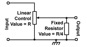
However, all is not lost. It turns out that if you put a resistor in parallel between the wiper and ground, the characteristic of the combination can be made to closely approximate logarithmic. The value of the fixed resistor determines the extent of the deviation from linear characteristic. I have seen recommendations that the fixed resistor should be 1/4 or 1/5 of the value of the potentiometer value (in the QCX case, the potentiometer is 5K so a fixed resistor of 1K would match these suggested values).
From http://www.learnabout-electronics.org/Resistors/resistors_09a.php:
Now look at the op-amp stage following the volume control, which is IC10b. This is configured as an inverting amplifier with a gain of 120. The input resistor R37 is 1K and this is also the effective input resistance of this amplifier.
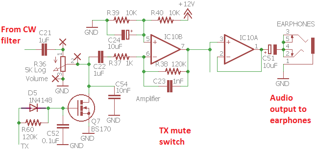
What this means is that by good fortune, the Linear track 5K potentiometer is loaded by 1K, which is to say, it already exactly meets the R/5 recommendation (you can find this mentioned on some audio forums). So despite having a Linear volume pot, the overall effect (combined with the 1K load of the following stage) results in a characteristic which is closer to a logarithmic curve than to a linear straight line.
Therefore the linear potentiometer is NOT the reason why you only using the lower 10% of the potentiometers adjustment range.
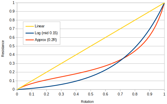
The degree of curvature of the logarithmic function is chosen according to what resistance you want at the potentiometer mid-range. According to http://benholmes.co.uk/posts/2017/11/logarithmic-potentiometer-laws a common choice is the resistance is 0.15 of the total, when the potentiometer is at the middle of its travel. This line is plotted in BLUE below. The RED line shows the effective shape of the QCX's Linear 5K potentiometer when loaded by the 1K input resistance of the following stage. You can see that the approximation is pretty reasonable!
The real reason...
The real reason is that the QCX receiver has a low noise front end, that gives it good sensitivity, and the overall gain of the receiver is a little on the high side. 100dB of gain from the antenna port to the audio output is a common rule of thumb for receiver gain during the design process. I was pessimistic and set the gain a bit higher, something like 106dB (depending on the adjustment of the BPF and other filter insertion loss).
Conclusion...
In conclusion there are two possible minor modifications that could be considered:
1) if you feel that the QCX at maximum volume is ear-splittingly loud and you would never ever use that much gain... then you need to reduce the gain of the QCX receiver. The easiest and best way to do this is to reduce the value of R38 (120K). You could half it, by taking on another 120K in parallel on the bottom side of the board. Or you could replace R38 with a lower value such as 47K or 56K. Or less! If you half the value of R38 that's like removing to the top 50% of the gain of volume control.
2) if you want a more aggressive logarithmic function (larger curvature) this is more closely approximated by a smaller resistor in parallel with the volume control wiper (wiper to ground). So then solder a 1K fixed resistor (for example) between the volume control potentiometer wiper and ground.
73 Hans G0UPL http://qrp-labs.com