By Hans Summers G0UPL, May 2025
General WSPR telemetry methodology and background
Way back over 10 years ago I followed the picoballooning efforts of Andy VK3YT https://picospace.net/ from Melbourne Australia, and Leo Bodnar M0XER https://leobodnar.com/balloons/ from UK, both of whom documented their flights very extensively on their websites. I was particularly intrigued by Andy VK3YT's flights around that time, which encoded telemetry into JT9 packets. A special version of WSJT-X software could decode these and upload them to his server for map plotting etc. The disadvantage was the need to recruit people to install this special version of WSJT-X and dedicate their radios to listening for his balloon flights.
Around beginning of 2015 Dave VE3KCL contacted me about flying a version of my Ultimate3S beacon transmitter with special firmware on a picoballoon flight. His first flight S1 is documented here: https://qrp-labs.com/flights/s1.html. Since the Ultimate3S could already transmit JT9 is was relatively easy to encode Andy VK3YT's telemetry protocol. It didn't quite work because the version of the protocol Andy was using was slightly different to his published protocol. But the concept was fine. The rest of Dave's flights are also documented here: https://qrp-labs.com/flights.html along with other participants and correspondents around that time. The flights developed into the U3B product development which evolved into the actual U4B product produced today.
My big idea around beginning of 2015 was that if I instead designed a telemetry protocol to run on WSPR (Weak Signal Propagtion Network, a propagation testing system created in 2008) see http://wsprnet.org then the entire huge network of WSPR monitoring stations would automatically, without even knowing it, receive and decode the WSPR packets, and upload them to the WSPR central database. From there I could extract the telemetry packets and decode them for mapping etc. The big advantage was that no special firmware was required, every one of the existing hundreds (or thousands) of WSPR monitoring stations around the world would be used and the changes of one being within range of the balloon transmissions are high.
The original telemetry encoding protocol was described on the S4 flight page and has almost not changed since then. The only change was in the interpretation of the battery voltage; and the penultimate least significant bit, the "GPS satellites" bit was repurposed to indicate an extended telemetry packet (for user-defined telemetry beyond the basic telemetry scheme).
WSPR transmits three fields: Callsign, 4-character Maidenhead Locator, and Power level. The callsign must adhere to strict rules:
- 1st character: Any of A-Z, 0-9 or Space (37 possible values)
- 2nd character: A-Z or 0-9 (36 possible values)
- 3rd character: Only a number 0-9 (10 possible values)
- Three more characters can be A-Z or Space (27 possible values)
The 4-character Maidenhead locator also has restrictions on the characters because the letters of the locator system do not run all the way from A to Z. The power levels can only be 0, 3, 7, 10, 13, 17, 20, 23, etc to 60dBm.
In this way the Callsign, Locator and Power can be heavily compressed into 50 bits, which are then encoded into 162 symbols, each of which is one of four frequency shift tones. The symbol transmission duration is 256 / 375 seconds, and the symbol tones have a frequency separation of 375 / 256 Hz (1.46 Hz) so the entire protocol modulation has a bandwidth of 6 Hz. The 162 symbols take 1 minute 52 seconds to transmit. The WSPR transmissions always start on the 2nd second of even minutes and there are a few seconds of tolerance in start time; additionally +/- 4Hz of frequency drift during the transmission can be tolerated. Each radio amateur band has 200 Hz of bandwidth which is allocated semi-officially to WSPR transmissions.
My protocol for transmitting telemetry over the top of this relies on re-purposing some of the callsign characters, and all the locator characters and power levels, to other data (the telemetry). The additional data in the telemetry packet is:
- 5th and 6th Maidenhead locator characters, therefore increasing the position location resolution to around 3km (instead of around 200km for a 4-character grid square)
- Altitude
- Voltage (from solar panels or battery)
- Temperature using the onboard LM75 temperature sensor
- Ground speed
- GPS status (0 = no GPS lock, 1 = GPS lock OK)
Channel system
Each WSPR transmission can only carry 50 bits of data. Some more bits are "lost" because the power level is a number from 0 to 60 dBm, but the system only allows 0, 3, 7, 10, 13, 17 etc to 60 dBm; the other numbers were reserved for future use, but since WSPR was created in 2008 they have never been used. I wanted to use as many bits for telemetry data as possible; clearly keeping the whole callsign as the actual flight operator's callsign would leave very few bits for telemetry. At the same time I needed somehow to be able to differentiate telemetry packets from the standard WSPR packets. And there would have to be a system for identifying different "channels" so that multiple flights could be run simultaneously.
The system I came up with fixed the first character of the callsign, for a particular channel, at 0, 1 or Q. The reason for this is that the International Telecommunications Union never allocates any callsign prefixes to any country or region, starting with 0, 1 or Q. (Note that originally we just used 0 and Q for the first couple of years). See https://en.wikipedia.org/wiki/ITU_prefix. Note that disputed territories or unrecognized nations have sometimes used the 1 prefix but this is very rare.
Furthermore since 3 channels would generally probably not be enough, other measures were also necessary. The 3rd character (which by the rules is 0 to 9) is also used for channel identification. Therefore if a standard WSPR transmission of callsign, locator, power might be:
G0UPL IO90 10
then a balloon telemetry transmission would be of the form:
CxCxxx xxxx xx
where C are channel ID encodings 0, 1, Q (first character) or 0-9 (3rd character) and the x's are all repurposed data where telemetry bits are encoded into the bit pattern instead.
Additionally a 10 minute transmission cycle was defined, where a balloon would transmit its standard WSPR packet, followed by the telemetry packet; then have 6 minutes remaining to do other stuff which would always include switching on the GPS to obtain a new position fix, but could also include further transmissions such as user telemetry packets, or other modes of transmissions. In a 10 minute transmission cycle, there are 5 possible start times (the time at which the standard WSPR packet is sent), transmission slots starting at 0, 2, 4, 6 and 8 minutes into the 10 minute transmission cycle. Therefore deciding on one of these 5 options to start transmissions is also a channelization.
Finally (and somewhat later) the 200 Hz wide WSPR sub-band, looks quite large when your transmission bandwidth is only 6 Hz and when you have a high performance TCXO (Temperature Controlled Crystal Oscillator) reference for your frequency synthesis. So a further four channels were obtained by dividing up this 200 Hz spectrum into five 40 Hz slices. The middle slice is not used because it tends to be more heavily used (many station operators didn't read that they can transmit anywhere in the 200 Hz, they just saw the "center frequency" published and dialed it into their radios). So this creates a further 4 channels, determined by which of the 4 frequency segments the transmission is received in.
Altogether this U4B channel system has 600 channels: that is to say, 600 balloons could all fly simultaneously on this telemetry system with minimal possibility of interference with each other:
- 3 possible first characters (0, 1, Q)
- 10 possible third characters (0 - 9)
- 5 possible start offsets, 2 minute slots in the 10 minute cycle
- 4 possible frequency segments (added around April 2022)
and hey presto, 3 x 10 x 5 x 4 = 600 channels.
Development
Since the WSPR protocol was published on the S-4 flight page in 2015, WSPR has largely been adopted as the standard way to track picoballoons, due to the very significant advantages of the system. Other telemetry systems such as APRS or other systems that run at VHF or UHF frequencies have limited range and are of no use when over oceans or unpopulated areas. Other weak signal (narrow bandwidth) modes do not have the global monitoring network.
Several developers made their own variations of the system, such as to keep the locator characters the proper "real" locator, which avoided spurious points appearing on the WSPR map however that problem was in any case largely solved when the WSPRnet website designers took note of the increasing use of WSPR for telemetry, and added a checkbox to exclude "special callsigns" used for balloon telemetry.
Dave VE3KCL's original flights used the 30m band (10 MHz) but later changed to 20m band (14 MHz) when it was found to offer more reliable propagation characteristics for this particular application.
The U4B protocol has become the standard for most picoballoon trackers in use today. It's quite easy to encode telemetry into the protocol and several website were designed for decoding (including plotting the path on a map).
Issues
One issue was how to allocate or reserve channels. I believe at least one website was set up to list channels that were in use. Originally just 20 channels (0, Q first character of callsign, 0 - 9 3rd character). I never liked the idea of one central authority figure deciding who should use what channel and depending on him to maintain and publish the list.
The first three channelization methods consisting of the 1st and 3rd callsign character, and choice of slot time, were always uncontroversial. That provided 150 channels.
But when I launched the U4B tracker for sale in April 2022 I also introduced the frequency segment channelization mechanism, increasing the number of available channels to 600. Each U4B tracker provided the operator a selection of 3 possible channels to use, which were derived from the unique serial number on each STM32 chip. So every U4B had its own unique set of 3 channels which were essentially random, and the chances were that a user would be able to choose one of these three channels that was not in use by anyone else; this therefore decentralized any channel allocation procedure.
The main problem with the frequency segments thing is that at first glance, it relies on the accurate frequency calibration of the WSPR monitoring stations. All these stations tune their radio receiver to the WSPR "USB dial frequency" which means WSPR transmissions appear as audio in the range 1400 - 1600 Hz, which is then fed to a computer where the WSJT-X software does the decoding and uploads the results to the WSPR database. But if the operator's radio is not accurately calibrated, in fact ANY error in its frequency, is translated to an error in the frequency that WSJT-X reports for each decoded transmission (stored in the WSPR database). There are a great many different receivers in the world and not all of them have very high accuracy specifications.
For example, the 20m (14 MHz) band has four possible balloon transmission frequencies:
- 14,097,020
- 14,097,060
- 14.097,140
- 14,097,180
If a balloon is transmitting for example, in the 2nd of these, 14,097,060 say; but a receiving station has a 50Hz callibration error so it writes its report to the WSPRnet database as 14,097,010 - then this will be in the ranger 000 - 040 which will be the FIRST of these four buckets, not the SECOND. It will therefore be interpreted by the tracker program which decodes all these telemetry packets and plots maps, as a different channel, and the report will be assigned to some else's balloon entirely. This is a loss of data for your balloon, AND a potential pollution of data for some other balloon flight operator.
Because of the ambiguity caused by the frequency calibration error of the receiving stations, the expansion of the channel system from 150 to 600 channels was a little controversial. Not everyone felt that 600 was or would be necessary. But since the U4B is by far the highest selling (and lowest cost, smallest, lightest) commercial tracker available, it's system is hard to ignore.
QRP Labs solution to the frequency error problem
To solve this issue with the errors of reporting stations, I developed a program which creates a cross-referenced matrix of all WSPR reception reports in one 2-minute transmission slot, and uses them all to average out errors.
How this works is as follows. Suppose a station A transmits at a certain frequency. Suppose 10 different stations all receive A and report him to the WSPRnet database, each report creating a new record in the database. My program reads out all the records in a 2 minute slot. It can average the reported frequencies of those 10 different reports of the same station A. Now the program has averaged out a substantial amount of the error; the mean of these numbers is very much closer to the real actual transmission frequency and there is no need to guess which of the 10 was correct, or know anything else about them.
Now I do that for every single transmitting station in the whole matrix. Each one has a mean average, which has reduced the errors. So now we have a quite good idea of the actual transmission frequencies of the transmitting stations. But what we really want to know is the calibration error of the RECEIVING stations. So the program goes through the list of receiving stations. A receiving station X will have received a number of transmitting stations at a certain frequency (according to X itself). But we also know the actual frequency of the transmitting station, from the averaging. So now we can compute the ERROR for each of the stations that X heard: it's frequency according to X, minus its frequency according to the average of everyone who heard it. We end up with a set of errors which are close to each other; but can be made even closer still by averaging those also.
So this is the basic concept... there are some details such as throwing severe outliers away, and excluding duplicate reports, or reports where only one station heard a station so "averaging" one result yielded no noise (error) reduction.
The program is written in C and it runs on the QRP Labs web server, every 2 minutes. For a transmission that started at 24 minutes past the hour (say), the transmission will finish 1 minute 52 seconds later; and the program will wait for all the WSPR receiving stations to call in to the WSPRnet server and upload their results, so it will run the analysis of that timeslot at 28 minutes past the hour.
Once the program has computed its receiver station error matrix, it runs through the list of reports looking for any that begin with 0, 1 or Q. These are balloon telemetry. It can now look at the frequency segment reported (after error correction), the timeslot of the transmission, the first character 0, 1 or Q, and the third character 0-9 and it knows EXACTLY which of the 600 channels the telemetry belongs to.
The final step requires, for creation of a tracking web page on the QRP Labs tracking page, that a QRP Labs account holder creates a record for his flight, that contains the callsign to be used, and the channel number. This maps the first WSPR transmission (standard WSPR) to the second (the telemetry packet), and if both are received successfully, allows us to obtain the full 6-character Maidenhead grid subsquare (2 or 3km precision), altitude, groundspeed, voltage, temperature and GPS status. All that is written into the QRP Labs database, and also to an HTML Google Map file, along with a telemetry header, which appears on the QRP Labs tracking page. See for example https://qrp-labs.com/track/1_Deneyap-2.html.
Practically speaking, the TCXO on the U4B is so good that the transmitted frequency error is normally within 1 or 2 Hz. The error matrix correction is astonishingly good (I was very pleasantly surprised by the results) and generally has an error of +/- 1 or 2 Hz also. Therefore a 40 Hz wide frequency segment is very wide indeed! In fact if more channels were required, if 600 was ever not enough, it would be very easy to narrow the frequency segments further to multiply the number of channels. And even if only one WSPR receiving station reports the balloon, as long as that station has reported other transmissions too (most of which are of course using much higher power than the U4B), then the error correction will be effective.
The two outputs of the matrix error correction, are the "actual transmit frequencies" and the "receiver error amounts" and these are written as HTML files on the server which are available on the QRP Labs website, for 20m band only (currently as at time of writing).
TX Freq: https://qrp-labs.com/im ages/wsprnet/txfreq.html
RX Error: https://qrp-labs.com/images/wsprnet/rxerror.html
Both pages are updated every 2 minutes.
Traquito tracking website solution to the frequency error problem
This is the Traquito tracler: https://traquito.github.io/search/spots/dashboard. Not everyone wants to write C programs on a server. Others are comfortable in other computer programming languages or with different tools. There are advantages and disadvantages to various approaches. The QRP Labs tracking way of handling this is in my opinion, very elegant. But it does require a C program to be run on a webserver, writing results into a database.
An on-the-fly method was developed by Doug KD2KDD which he called "Fingerprinting". It does not require any static web page, any C program running on a server, any database. It runs entirely from a SQL extract of data from the WSPR.live database (a reflector of the data in the real WSPRnet database). One of the fields to enter at the above link is the callsign of the flight operator, the other is the U4B channel number.
When the query is run, the "Fingerprinting" method looks for reports of the specified operator callsign in the appropriate timeslot (determined from the channel number), and looks for corresponding telemetry packets reported in the subsequent 2 minute transmission slot, having the correct 1st and 3rd character for the specified channel number. What it CANNOT do is determine which of the four frequency segments the telemetry packet belongs in, because the Traquito system doesn't do any correction of receiver station calibration frequency errors. Therefore there is a one-to-four ambiguity which must, by some means, be resolved, in order to correctly resolve the full 600 channels.
"Fingerprinting" does the matching of the first (standard) WSPR packet to the second (telemetry) packet by looking at the reported frequency of both packets from the same receiving station. When both packets are reported with a similar (close, at least) frequency, this means that they very likely belong to the same transmitter. Assuming that any frequency transmission error is fixed, and so is the calibration error of the receiver station.
There are two main disadvantages to this system.
FIRSTLY, it requires that at least one receiving station reported both the standard WSPR packet, and the telemetry WSPR packet, so that the frequencies can be matched together ("fingerprinting"). At least if a receiving station receives one transmission, this shows that it is at least within range for the propagation conditions. But in weak conditions where reception is marginal, this may not be enough. Or, in situations where there are other stronger interfering stations on the same frequency as the balloon, in a particular transmission slot. In some areas of the world where the density of receiving stations is low, it may well be the case that only one single station reports a balloon's standard WSPR transmission, and that a DIFFERENT station reports the telemetry transmission. In these cases, the QRP Labs tracking is able to still decode the full telemetry, whereas the Traquito tracking system would not be able to match up the two packets so the data would be lost.
SECONDLY, and less seriously, an operator who flies multiple balloons is slightly more restricted, if he wishes to use Traquito tracking, because he must make sure that none of his flights are on the same callsign + 1st and 3rd character + timeslot combination, and only differ in their frequency segment - because Traquito is not able to separate those, according to my understanding. This slight restriction however, is not likely to be much of a disadvantage.
Experiment to determine the relative disadvantage of Traquito tracking
In December 2024 I decided to analyze Dave VE3KCL's U4B-40 flight which is plotted on the QRP Labs tracking here: https://qrp-labs.com/track/495_U4B40.html. At that time, U4B-40 has been flying for almost 9 months, and had completed (at least) 12 circumnavigations and criss-crossed the entire Northern hemisphere multiple times. I thought that this large dataset would be reasonably representative.
For sure, an enduring balloon will fly over heavily populated areas with relatively dense radio amateur populations, where a balloon will have so many reports that there is never a situation where there is not at least one station reporting both standard and telemetry packets. However the balloon may also fly over sparsely populated areas where it is much more difficult to get reports, and where the Traquito disadvantage becomes more prominent. By analyzing the entirety of such a long flight I believed that I would most likely average out any abnormalities and give a fair representation of the actual disadvantage amount.
All the position reports are recorded in the QRP Labs database so I was able to extract a complete dataset of all logged records of the U4B-40 flight. from the launch on 26-Mar-2024 until the analysis date 10-Dec-2024. Fortunately the QRP Labs database schema also contains a column that lists all the callsigns that received each report. I then wrote some Excel VBA code to identify each record in the database for which there was no intersection of the set of receiving stations logging the standard WSPR transmission, with the set logging the telemetry transmission.
The results were that there were 12,469 records in the U4B-40 dataset whose standard and telemetry packets had both been reported. Of those, there were 720 records with no intersection. In other words, 720 records which Traquito tracking would necessarily have lost. QRP Labs tracking obtained 6.1% more full telemetry records than Traquito tracking could have done with the same dataset.
Note that any large balloon tracking dataset contains a certain level of noise: spurious noise decodes do sometimes occur in WSPR although there is heavy forward error correction. However, such noise decodes would affect the entire dataset equally, not just the 720 extra records. Furthermore, it was easy to examine the 720 records manually; the noise decodes are easily identified because of spurious telemetry data (altitude, temperature etc) which are substantially different from adjacent records and would be physically impossible to occur in reality. For example if you see a record whose altitude is 15km, and all the others are in the normal flight range very close to 12km, you know 100% for sure that this balloon can never get as high as 15km, so this MUST be a false decode. But it was possible to easily find these in the 720 records and calculate that even if there were no errors at all in the other 12,000-odd, it still would make no material difference to the 6% advantage figure.
If you would like to see the raw data, here is the .csv file.
Another interesting outcome of the analysis was a frequency distribution of the reception reports:
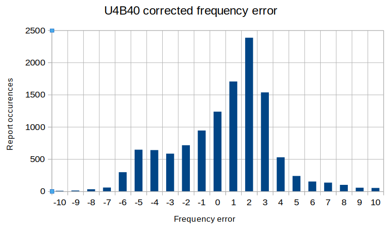
This appears to show a +2Hz systemmatic transmitter frequency error, which is perhaps caused by a temperature induced drift from the room temperature GPS calibration of the TCXO, to the temperature at altitude. Some of the variance must also be caused by slight crystal frequency drift due to temperature-induced changes over the course of the day: the temperature differential experienced by the U4B tracker board in flight is quite extreme. Overall you can see that the frequency error correction algorithm really does an extremely good job and it would be perfectly feasible to double the number of channels to 1200 by halving the frequency segment size to 20 Hz.
This analysis attracted heated debate on the picoballoons forum https://groups.io/g/picoballoon in December 2024, merely calling it "heated" is one of the understatements of 2024.
Analysis and opinion
The topic came up on the picoballoons forum after there was a proposal to abandon channelized telemetry altogether (and "heated" subsequent discussion). I am not in favour of this because I believe that in many cases, structure increases communications efficiency.
Several examples. If you have a highway which has 10m wide tarmac in each direction, what do you do? You divide each direction into two lanes, and you set up a set of rules so that road users can safely use both lanes to ensure effective traffic flow. Not everyone drives at the same speed. So now faster people can go in one lane and slower in another. Or people can overtake.
If you have very low traffic, everything seems to work fine whatever you do, wherever you drive, rules or not. (Note: If you happen to pass the Jandarma, hiding in their little blue van behind a large and fortuitously positioned roadside bush, and they happen to see you not in the correct lane, then they will not like it, even if there is no other traffic around. Don't ask me how I know). If traffic flow is heavy, then the well-organized system of rules dramatically improves safety AND efficiency, the road area is used optimally.
Or say you want to paint a wall white. You use a large tin of paint and a paint roller. Why do you paint in stripes? Not randomly pulling the roller across the wall in all random directions? Because painting in stripes is an organized way to cover the entire area as efficiently as possible. You don't have to cover the same area multiple times and you don't risk leaving unpainted gaps. If your paint roller was to follow a random path across the wall, it would take an awful lot more paint to cover the whole wall, because many areas would get painted twice (or more).
So very often, good structure and organization, in appropriate situations, can improve efficiency substantially. I think weak signal telemetry communications is one of these cases. Even WSPR itself is organized as far as possible, by having timing requirements (starting on the 2nd second of even minutes) and rules about the fields which are encoded, so that it is encoded as efficiently as possible. There are other protocols such as OPERA that does not enforce timing; with low activity, it makes no difference but in a crowded band, random start times would create a lot more potential for interference.
Regarding the telemetry matching itself, it is my firmly held opinion that a 6% loss of data is a too significant disadvantage to ignore. Frequency calibration errors are a problem. The error correction algorithm is an elegant neat solution to the problem. In picoballooning, getting our data is hard. We want to grab a few mW from thousands of km away. It needs all the help it can get. Just because a particular technical solution does not conform to some arbitrary limitation such as, it is not using a programming language we are familiar with, or it requires a server infrastructure but we prefer an entirely javascript based solution - these artificial objections are not a good enough reason to throw away 6% of data, and not a good enough reason to obstruct technical progress.