1) LCD backlight adjustment in configuration parameter [U3 only]
2) DDS Modification for 6m [U3 only]
3) DDS threshold adjustment [U3 only]
4) DDS auto-threshold adjustment [U3 only]
5) More transistors, more power
6) More power on MF and LF bands
7) A simple amplifier for the U3 for 136 & 472 kHz by Toni HB9ASB
8) SlowHell in the IZ8BLY program
9) Ultimate3 as GPS-disciplined frequency reference [U3 only]
10) Make your Ultimate3 11-band!
11) Potentiometer tuning for the Ultimate3
12) U3 to U3S conversion [U3 only]
13) Heat-sink for Ultimate, by Per LA9DTA
14) Secure antenna connection, by Per LA9DTA
15) U3S high frequency stability, by Jon Ove LA3JJ
16) 2m LPF for U3S, by Tor SM6FWF
1. LCD backlight adjustment in configuration parameter [U3 only]
(Note: The U3S kit provides an A3 pad. The option is discussed in the assembly manual, to jumper that to A0. This results in software control of the brightness, as achieved by this U3 modification).
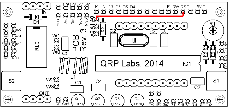
In firmware v3.05 and above there is a configuation parameter called "Backlight", which has a value 0 to 9 (default is 9). This parameter controls the brightness of the LCD screen's backlight LED from off (setting = 0) to full brightness (setting = 9). In order for this to work, the modification shown below is required (click for larger image). You should remove whatever jumpers you have installed at A0, A1 and A2. Instead, make a wire connection from A0 to the RS connection (pin 4) of the LCD module, as shown. This diagram shows PCB revision 3. However, this will work on all PCB revisions. The A0/A1/A2 pads are in a slightly different location on earlier PCB revisions, but the modification is similar.
Brightness control is achieved by Pulse Width Modulation (PWM) of the signal at the RS pin by the microcontroller firmware, when the RS pin is not in use for communicating with the LCD. The pulse width modulation frequency is 610Hz. It should be noted that the variation in supply load might put noise on the power supply line and this could get into other equipment e.g. a radio receiver. So if you hear something, try switching to backlight brightness 9 and see if the interference stops. Backlight brightness 9 is fully on, no PWM, no pulsing. The duty cycle for each brightness level is set logarithmically and is, I think, consistent with how the human eye judges brightness: 0 = Off; 1 = 1/256; 2 = 1/128; 3 = 1/64; 4 = 1/32; 5 = 1/16; 6 = 1/8; 7 = 1/4; 8 = 1/2; 9 = On.
Note that the U3 LCD's backlight LED current is about 30mA. If you replace the LCD module with a different one then please ensure that its backlight current consumption is not too high, since the LED is being powered directly from the AVR's I/O pin.
2. DDS Modification for 6m [U3 only]
(Not applicable to the U3S, which does not use the AD9850 DDS module)
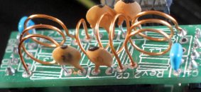
Simple modification to the DDS module that allows operation on 6m (but spectrum is not very clean, so not recommended to go on air on 6m). The modification also improves output spectrum and output power on all other bands. Read more...
3. DDS threshold adjustment [U3 only]
(Not applicable to the U3S, which does not use the AD9850 DDS module)
The blue potentiometer on the AD9850 module sets the threshold of the DDS comparator and is responsible for turning the sinewave output of the DDS into a squarewave to switch the BS170 PA transistor. This potentiometer is already adjusted when the kit is supplied. However sometimes it needs tweaking for best operation on higher bands e.g. the 10m band. Unfortunately, the setting is very sensitive, it is difficult to adjust it to just exactly the right point. Replacing that blue potentiometer with a mult-turn potentiometer makes it easier to adjust.
4. DDS auto-threshold adjustment [U3 only]
(Not applicable to the U3S, which does not use the AD9850 DDS module)
Why not get rid of the blue potentiometer altogether, by following the advice of the AD9850 datasheet? MORE SOON
5. More transistors, more power
Higher power output from the U3 kit is available by adding more BS170 transistors in parallel with the supplied BS170 PA transistor. There is space on the PCB for two additional BS170 transistors and they are available also in the QRP Labs shop. However, merely adding BS170 transistors isn't generally enough to significantly increase the power output. The Source-Drain resistance of a switched-on BS170 is already very low and putting three in parallel doesn't help much. Furthermore, you will also be trippling the gate capacitance load on the DDS comparator output, which is likely to make the switching edges rise/fall times slower, and decrease the efficiency of the PA.
In order to truly obtain benefit from adding more transistors in parallel, you will also need to increase the PA supply voltage. Please be sure to cut the link between the PA supply and the +5V supply of the U3, before increasing the PA voltage! I have heard so many people's sad story of how they fried their U3 by accidentally applying too much voltage, and leaving that link connected is one way to do just that.
Increasing the PA supply voltage will increase the output power considerably. You can try up to 13.8V (some more results on this topic, below in the next section. The heat dissipation will be shared between the three BS170 transistors. You can add a heatsink as well, the transistors have been located next to the board edge with their flat sides facing outwards, precisely to facilitate adding a heatsink if desired.
6. More power on MF and LF bands
People have noted that the power output unexpectedly drops off on the lower bands. The reason for this is the low value (10nF) of the capacitor C5 which couples the RF from the PA to the LPF circuit. At low frequencies the reactance of this capacitor increases and this causes loss of power. A very simple modification, suggested by several people, is to replace the capacitor C5 with a higher value, such as 100nF (0.1uF). You don't need to bother to remove C5, unless you are a cosmetic perfectionist. You can just solder the 100nF capacitor in parallel with C5 e.g. on the underside of the board.
Toni HB9ASB has made some measurements following these modifications and writes: "As I’m interested in the LF/MF bands I have modified the Ultimate 3 for max performance on 2200/630/160 and 80m. The results are very interesting. The ultimate 3 is a real power house! ... I think the Ultimate has still a lot of potential for experiments and modifications. It is a wonderful device!"
Toni added 100nF ceramic capacitors across all 10nF capacitors for better blocking and coupling, and replaced the choke in the PA with a R10/N30 core with 25 turns. To get maximum power output on each band the blue DDS threshold potentiometer had to be tweaked individually for each band, but it should be possible to find a compromise position. Toni made some measurements of power output with 5V and 13.8V PA voltage, and PA efficiency at 13.8V supply (after the modifications, of course!)
| Band | 5V power | 13.8V power | Efficiency (13.8V) |
| 10m | 135mW | 650mW | 28% |
| 80m | 360mW | 2.9W | 84% |
| 160m | 400mW | 3.2W | 83% |
| 630m | 370mW | 2.3W | 71% |
| 2200m | 260mW | 540mW | 17% |
Toni reports that the transistors do get a little bit hot but with the high efficiency, it is not necessary to use a heat sink except on 2200m. The DDS potentiometer setting was very critical on the 10m band, with only one small range where a proper signal could be obtained on the spectrum analyser.
7. A simple amplifier for the U3 for 136 & 472 kHz by Toni HB9ASB
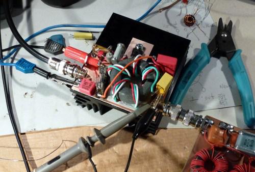
A neat amplifier by Toni HB9ASB for the U3 for LF/MF bands provides 25 to 50 Watts output. CLICK HERE for more information.
8. SlowHell in the IZ8BLY program
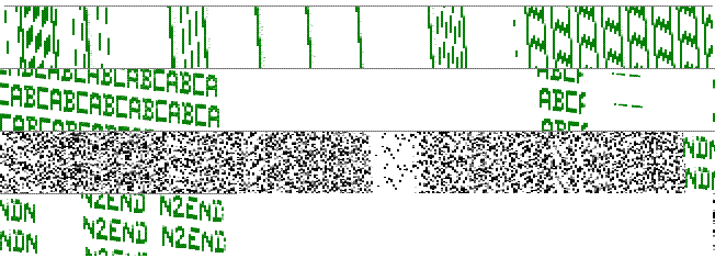
An email from Lou N2END, who found out something I did not know: Just a quick note to tell youy that the U2 kit I have is a lot of fun. Today, I figured out that by using SlowHell at a speed of 31 s/character and FSK = 0, I can send very slow single tone Hellschreieber that can be received using the IZ8BLY program on the setting "SlowFeld Beacon receiver". Here's a screenshot from Lou:
9. Ultimate3 as GPS-disciplined frequency reference [U3 only]
(This firmware has not yet been updated to be able to use the Si5351A synthesiser. So this modifcation cannot be done on the U3S).
A modified beta firmware version turns the U3 kit into an accurate GPS frequency reference (about 0.03Hz accuracy). For output frequencies not more than 8MHz, no hardware modification is needed. For output frequencies above 8MHz you must make a modification, involving cutting a track and using an external divider chip. Read more here...
10. Make your Ultimate3 11-band!
Here's a nice modification by Per LA9DTA, whose Ultimate3 now has 11 low pass filters plugged in and can cycle through them all. The modifiction makes use of the Aux parameter in each of the mode-setting screens on the U3 (requires firmware v3.05 and above).There are some problems (two relays come on at once) with Per's mod. A subsequent update by Michael DK7MF adds some diodes and makes it all work properly. Read more here...
11. Potentiometer tuning for the Ultimate3
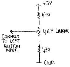
This modification allows the Ultimate3/3S kits to be tuned using an ordinary cheap plain potentiometer. The idea is that at the centre position no tuning happens. As soon as you turn right a little, the frequency starts increasing slowly, until you move the knob back to the centre. if you turn a little further right, the frequency increases more fast, etc. Similarly, frequency decreases for an anti-clockwise angular shift relative to the centre position.
This modification is useful for example, for people using the kit as a CW transmitter, because it allows easy tuning of the frequency, without need to manually key in the frequency in the configuration menu.
To make the modifiction, connect the ends of the potentiometer track to Gnd and +5V, but in series with a 470 ohm resistor. One each end, to Gnd and 5V. That's all. The wiper of the potentiomer is to be connected to the Left button input. The tuning potentiometer and the left button both share the same microcontroller pin. When the U3 is operating, the knob can be used for tuning purposes.
The knob rotation is divided into 28 divisions. So very roughly each division is about 11 or 12 degrees of angle. Ordinarily the knob should be set to the centre of its track. While in the centre two positions, no tuning occurs. If you turn the knob to the right by one division, the frequency will start to increase by 1Hz every time. It carries on increasing until you turn the knob back to the centre. That happens 5 times per second. So 5Hz/second. If you turn the knob more to the right, tuning is faster. Turn to the left, the same thing happens, now decreasing the frequency of course.
The frequency steps are 1, 2, 4, 8, 16, 32, 64, 128, 256, 512, 1024, 2048 so at the maximum end of the potentiometer track, it will be tuning at a rate of 10,240Hz / second.
Note that component values can be varied. The rule is that the fixed resistors (here 470 ohms) should be approximately 1/10th the value of the potentiometer (here 4.7K). A 5K resistor would work fine instead of the 4.7K resistor, it is close enough to 10x the 470 ohm fixed resistors. Other potentiometer values could be used too, with appropriate 1/10th fixed resistors. I recommend staying in the range 1K to 10K though.
12. U3 to U3S Conversion modification [U3 only]
The Si5351A Synthesiser module kit can be plugged into a U3 instead of the supplied AD9850 DDS, as long as firmware v3.07 or above is installed. However, the power output is lower with the Si5351A because the output is 3.3V, compared to the AD9850's 5V. The modification page describes the minor changes needed to restore the output power, and optionally carry out the full conversion to U3S. Read more, click here...
13. Heat-sink for Ultimate, by Per LA9DTA
"Here is a heat-sink mod, it is made out of 5mm aluminium. The BS170 are glued to in the holes before assumbling, using a special heat sink compound. When assembling use a piece of electrical tape on the bottom side. Add a small drop of heat sink compoind in each hole. Gentrly push and rotate the transistors in to the correct place. Remove the excess heat sink compound and let it dry for a while. The holes should be a little more than 4.5mm, buf if after making the holes, you pull the drill bit sideways a little, the holes will grow to 4.6mm."
14. Secure antenna connection, by Per LA9DTA
Several constructors have noted that the connection of the antenna to the PCB can be the weak point. Coax cable tends to be heavier/stiffer than the other wires involved, and more strain is put on the connection. Per LA9DTA uses the solution shown below, with a tie-wrap to hold the coaxial to a newly drilled hole. This keeps the soldered connection still. Teflon cable, normally a military type, should be used to avoid melting the cable dielectric and causing a short.
15. U3S Frequency stability, by Jon Ove LA3JJ [U3S only]
The Si5351A Synthesiser module kit can be used with the U3S kit to get 0Hz drift reports on 10m WSPR, even without the OCXO, by using a heatsink on the crystal, insulation foam around the synth, and park modes in the U3S. Read more, click here...
16. 2m LPF for U3S, by Tor SM6FWF
Tor SM6FWF built a 2m LPF on the usual QRP Labs LPF PCB, using air-cored inductors, 3 turns wound on 6mm diameter. Read more, click here...
