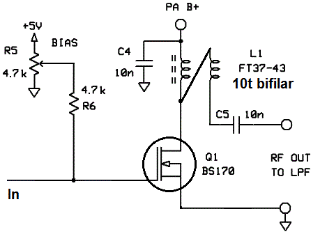
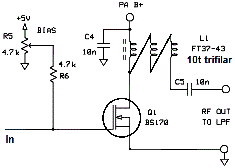
Some experiments on the U3S PA circuit were done, replacing the L1 25 turns FT37-43 with 10 turns Bifilar-wound and Trifilar-wound transformers. The bifilar transformer output significantly boosts the output power of the U3S, from typically 200mW to typically around 350mW. There is an even more dramatic increase in power if the PA bias voltage (R5 adjustment) is increased further.
Bifilar and trifilar transformers
A quick reminder. A "bifilar transformer" is made by taking two equal lengths of wire and twisting them together tightly. You want perhaps something like 8-10 twists per inch (3-4 twists per centimetre), although it is not very critical. You then wind this twisted wire 10 times through the core, to create a 10-turn bifilar transformer. A trifilar transformer is similar, but now you twist together THREE pieces of wire.
The tricky part is keeping track of which wire is which. It helps if you have different coloured enamel on the wires. I happened to have green wire and orange wire, which makes the bifilar transformer easy. When it came to the trifilar transformer, only measuring continuity with the DVM helps to identify which winding is which.
Consider first the bifilar case. In the diagrams, the top end of the transformer in the diagram, is one end of the windings. The "primary" winding is connected between PA B+ and the Q1 MOSFET as usual. The "secondary" winding has its top end (same end of the wire as the PA B+ connection) connected back to the bottom end of the primary. The output of the transformer is the bottom end of the secondary. This is actually much easier to see in practice, than describe in words... The trifilar wound transformer follows the same general idea but now you are connecting back both secondary wires.
About wire twisting...
Twisting the three pieces of wire in a trifilar can be a bit tedious. When I do it by hand I typically tie one end of the three pieces of wire round one screwdriver, and the other end around another screwdriver, then keep twisting them around relative to each other. But my favourite method involves a miniature 12V "dremel"-type drill. Here I tie one end of the wires to something solid in the lab. The other end I tie in a knot and clamp it in the drill. Then give it the shortest possible burst of power. It can twist a meter of trifilar wire very well in just a fraction of a second. So be careful with it. I find that it helps to be winding say 0.5 or 1m of wire, even if you only want 15cm for your 10 turns... then just keep the spare section for next time you need trifilar wire. Again to emphasise: the process of twisting the wire like this is REALLY fast, so only power on that drill for a very short time!
PA circuit diagrams
As a reminder, click here for the U3S circuit diagram.
Below are the two modified PA sections, one for the bifilar output transformer and one for the trifilar output transformer. Q2 and Q3 have been removed in these diagrams to make them more clear. All my experiments used a single BS170 PA transistor at 5V PA voltage. Don't forget the C1 coupling capacitor (not shown here) at the input which makes sure the RF input is AC coupled to the Q1 gate, so that the DC level at the gate is set by the R5 bias potentiometer.
Bifilar-transformer PA:

Trifilar transformer PA:

Results
The PA was tested on 160m (2.0MHz), 80m (3.5MHz), 30m (10.0MHz), 12m (24.0MHz) and 6m (50.0MHz). For the purposes of comparison with the "base case" U3S PA, I have used the power values from the earlier U3S PA bias study. In all cases I used a 50-ohm dummy load connected after the Low Pass Filter. Power measurements are calculated from the peak-peak output voltage across the dummy load, as measured on a 100MHz oscilloscope with on-screen cursor function. Two different power levels were measured, at two different PA biasing points (potentiometer R5 adjustment), as follows:
1) Peak power: this is the setting of R5 which results in the highest power output. As mentioned in the U3S PA bias study, this results in highest power but also high harmonic content output, and inferior efficiency. Lastly of course, the transistor might be getting very hot very quickly.
2) "Safe" power: this is the setting of R5 at which the PA current increases slightly over zero, during key-up (no input signal). In other words the "idle" current is just about positive. As mentioned in the U3S PA bias study, this is a good way to determine the best R5 setting (PA bias): it is not the absolute highest power but it does typically result in a cool-running BS170, and a clean output (low harmonic content), and good efficiency. For this particular transistor the bias level was 2.54V (it will vary from device to device).
Note: [For unspecified reasons,] the earlier measurements were on 10m band, this time these are on 12m band.
| Band | Base peak mW | Base safe mW | Bifilar peak mW | Bifilar safe mW | Trifilar peak mW | Trifilar safe mW |
| 160m | 238 | 214 | 912 | 312 | 476 | 135 |
| 80m | 224 | 198 | 837 | 351 | 508 | 163 |
| 30m | 200 | 189 | 628 | 351 | 515 | 183 |
| 12m | 400 | 250 | 267 | 149 | ||
| 10m | 152 | 123 | ||||
| 6m | 98 | 58 | 111 | 55 | 73 | 45 |
Charts
The results are plotted graphically below, on a logarithmic frequency (horizontal) axis. The first two graphs are in mW, the second two are the equivalent in dBm.


Conclusions
1) Apparently the bifilar output transformer significantly increases the U3S power output across the whole of HF.
2) The trifilar output transformer is not as good as the bifilar, particularly when looking at the "safe" power, it does worse than the standard U3S
3) Both bifilar and trifilar lose any benefit at all at 6m (output power is lower than measured with the standard U3S). I expect that the type -43 toroid material is too lossy at 6m frequency.
Disclaimers
No BS170 transistors were harmed during this experiment, although some discomfort was experienced (toasty temperatures). No dummy load resistors were harmed either, and since the workbench was already set up for testing much higher power PAs, the dummy load resistors were big enough to not even suffer any discomfort...
Further investigation
Obviously there are loads of variables which could be changed, and only so many hours in the day. Other things that could be measured:
1) Effect of higher PA voltages
2) Effect of having more BS170 transistors in parallel
3) PA efficiency measurement comparisons between standard U3S, bifilar and trifilar transformer output cases
4) Harmonic content of the output
Bifilar modification by Kelly Keeton
Kelly Keeton modified his U3S for Bifilar PA operation. He writes: "I wound the coil and was able to stuff two leads thru a single thru hole for the connection to Q1. Since there was lots of room on the PCB I just drilled another hole for the connection to C5".

